NTI R 1275 Danner Dr Tel:330-562-7070 NETWORK TECHNOLOGIES Aurora, OH 44202 Fax:330-562-1999 www.nti1.
WARRANTY INFORMATION The warranty period on this product (parts and labor) is one (1) year from the date of purchase. Please contact Network Technologies Inc at (800) 742-8324 (800-RGB-TECH) in the US and Canada or (330) 562-7070 (worldwide) for information regarding repairs and/or returns. A return authorization number is required for all repairs/returns. COPYRIGHT Copyright © 2003 by Network Technologies Inc. All rights reserved.
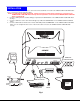
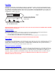
INTRODUCTION INTRODUCTION The UNIMUX-USBV-2 (formerly referred to as KEEMUX-USBV-2U) USB KVM switch allows one user to access two USB CPUs with only one USB keyboard, USB mouse, and 15HD VGA monitor. Internal microprocessors allow both CPUs to boot simultaneously and error-free. Port selection is accomplished by a front panel push button or commands typed on the keyboard.
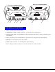
R e a r V ie w o f U N IM U X -U S B V -2 N T I o f U N IM U X -U S B V -2 U N IM U X F r o n t V ie w R N e t w o r k T e c h n o lo g ie s In c N T I N e t w o r k T e c h n o lo g ie s In c U N IM U X 1 R - 2 + 3 4 6 5 7 FEATURES AND FUNCTIONS FEATURES AND FUNCTIONS 1. 5VDC- connection jack for the AC adapter 2. USB DEVICES- USB type A female receptacles- for connection of user USB device(s) 3.
INSTALLATION INSTALLATION 1. It is not necessary to turn OFF power to either of the CPUs that will be connected to the UNIMUX-USBV-2 USB KVM switch before connecting or disconnecting any cables. NOTE: If a CPU needs to identify a keyboard, it will be necessary to power ON the CPU after it is connected to the UNIMUX-USBV-2 USB KVM switch and only after the keyboard is connected and the UNIMUX-USBV-2 USB KVM switch is powered ON. 2.
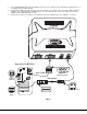
N T I R 7. N e t w o r k T e c h n o lo g ie s In c 6. Using a USB-AB-x-MM cable connect the USB type A device port of a USB CPU to the USB type B port labeled "CPU 1" on the UNIMUX-USBV-2 USB KVM switch. Using a VEXT-xx-MM connect the video port of the same USB CPU connected in step 5 to the female 15HD port labeled "VIDEO 1" on the UNIMUX-USBV-2 USB KVM switch . Be sure to tighten the two screws on the cable connector to the UNIMUX-USBV-2 USB KVM switch securely.
POWER-UP SEQUENCE The UNIMUX-USBV-2 USB KVM switch can be powered at any time. The CPUs can be powered at any time although if a CPU needs a keyboard and/or mouse at power-ON it should be powered after connecting to and powering-ON the UNIMUX-USBV-2 USB KVM switch. USB devices (keyboard and mouse) can be hot plugged to and from the UNIMUX-USBV-2 USB KVM switch at any time. Remember, the last attached device is the active one.
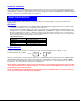
Command Mode Function: Keystroke: Increment Port Decrement Port I or (select the next higher port ex. 01 02) D or (select the next lower port ex. 02 01) KEY SYMBOLS LEGEND: or + - PRESS EITHER KEY CHORDED SEQUENCE- PRESS CONSECUTIVELY AND KEEP KEYS PRESSED UNTIL ALL ARE PRESSED. PRESS CONSECUTIVELY (When toggled to ON, Scan Mode will be indicated the LED for only the active CPU flashing ON and OFF .) Toggle Scan Mode ON and OFF S Sets scan time-out period for each port.
Scan Mode Scan Mode is indicated by a flashing CPU port LED. In Scan Mode the switch scans back and forth between ports making the CPU connected to the port with the flashing LED active. That connected port will remain active while in use. When the connected port becomes idle for the user selected time out period (default time is 5 seconds), the UNIMUX-USBV-2 USB KVM switch will connect to the other CPU port. See Command Mode section on page 5 for configuring the scan time out period. Fig.
KEYBOARD KEYBOARDFEATURES FEATURES The keyboard configuration of each CPU is saved in the NTI UNIMUX-USBV-2 USB KVM switch. For example, if the CPU attached to Port 2 had CAPS LOCK and NUM LOCK selected the last time that CPU was accessed, then they will automatically be set when that CPU is accessed again. Keyboard-To-Computer Translation (See Fig. 4 on page 9 for reference.
Fig.
It is also possible to configure the UNIMUX-USBV-2 USB KVM switch to emulate a specific international Sun keyboard regardless of what actual keyboard is connected. This is recommended when the CPU needs the layout code (i.e. a SUN CPU) and the keyboard doesn't have an explicit layout code (i.e. some Windows keyboards). To do this, manually set the UNIMUX-USBV-2 USB KVM switch to indicate the international keyboard identification number to the CPU using the following procedure; 1. 2. 3. 4. 5. 6. 7. 8. 9.
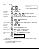
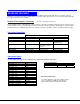
TECHNICAL TECHNICALSPECIFICATIONS SPECIFICATIONS USB Type B USB Type A Pin # Signal Pin # Signal 1 2 3 4 +VCC - DATA +DATA GND 1 2 3 4 +VCC - DATA +DATA GND Mating face of a USB Type B Female VGA Video Pin # 1 2 3 4 5 6 7 8 Signal RED GREEN BLUE ID2 TST RED GND GREEN GND BLUE GND Mating face of a USB Type A Female Pin # 9 10 11 12 13 14 15 Mating face of a 15HD female VGA VIDEO 4 5 2 1 10 1 3 2 3 4 Signal NC GND ID0 ID1 HS VS ID3 15 14 3 9 2 8 13 12 1 6 7 11 4 Barrel Power
MODEL NO: UNIMUX-USBV-2 SERIAL NO.