NTI R 1275 Danner Dr Tel:330-562-7070 NETWORK TECHNOLOGIES Aurora, OH 44202 Fax:330-562-1999 www.nti1.
WARRANTY INFORMATION The warranty period on this product (parts and labor) is one (1) year from the date of purchase. Please contact Network Technologies Inc at (800) 742-8324 (800-RGB-TECH) in the US and Canada or (330) 562-7070 (worldwide) for information regarding repairs and/or returns. A return authorization number is required for all repairs/returns. COPYRIGHT Copyright © 2003 by Network Technologies Inc. All rights reserved.
TABLE OF CONTENTS INTRODUCTION............................................................................................................................................................. 1 Available Options:........................................................................................................................................................ 1 MATERIALS ...........................................................................................................................................
TABLE OF FIGURES Figure 1- Connect the devices and Monitor .................................................................................................................... 3 Figure 2- Connect a CPU ................................................................................................................................................ 4 Figure 3- Country Codes for international SUN keyboards.............................................................................................
INTRODUCTION INTRODUCTION The UNIMUX-USBV-4 (formerly referred to as KEEMUX-USBV-4U) USB KVM switch allows one user to access four USB CPUs with only one USB keyboard, USB mouse, and 15HD VGA monitor. Internal microprocessors allow all CPUs to boot simultaneously and error-free. Port selection is accomplished by a front panel push button or commands typed on the keyboard. Available Options: • • • • UNIMUX-USBV-2 USB KVM switch with connections to access two USB CPUs rather than four.
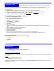
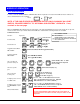
F E A T U R E S A N D F U N C T IO N S R e a r V ie w o f U N IM U X -U S B V -4 F r o n t V ie w 6 N T I N E T W O R K T E C H N O L O G IE S IN C O R P O R A T E D R V ID E O 5 1 2 7 5 D a n n e r D r iv e , A u r o r a O h io 4 4 2 0 2 4 V ID E O 3 V ID E O 3 3 0 -5 6 2 -7 0 7 0 2 N T I M O N IT O R 1 1 0 3 w w w .n ti1 .
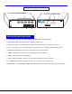
INSTALLATION INSTALLATION 1. It is not necessary to turn OFF power to any of the CPUs that will be connected to the UNIMUX-USBV-4 USB KVM switch before connecting or disconnecting any cables. NOTE: If a CPU needs to identify a keyboard, it will be necessary to power ON the CPU after it is connected to the UNIMUX-USBV-4 USB KVM switch and only after the keyboard is connected and the UNIMUX-USBV-4 USB KVM switch is powered ON. 2. 3. 4.
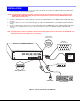
5. 6. 7. Using the USB cable ends of a USB-VEXT-xx-MM cable connect the USB type A device port of a USB CPU to the USB type B port labeled "CPU 1" on the UNIMUX-USBV-4 USB KVM switch. Using the 15HD male video connector ends of the same USB-VEXT-xx-MM, connect the video port of the same USB CPU connected in step 5 to the female 15HD port labeled "VIDEO 1" on the UNIMUX-USBV-4 USB KVM switch . Be sure to tighten the two screws on the cable connector to the UNIMUX-USBV-4 USB KVM switch securely. See Fig. 2.
Power-Up Sequence The UNIMUX-USBV-4 USB KVM switch can be powered at any time. The CPUs can be powered at any time although if a CPU needs a keyboard and/or mouse at power-ON it should be powered after connecting to and powering-ON the UNIMUX-USBV-4 USB KVM switch. USB devices (keyboard and mouse) can be hot plugged to and from the UNIMUX-USBV-4 USB KVM switch at any time. Note: If the DDC support option is installed, the UNIMUX-USBV-4 and the monitor must be powered up before any CPUs are powered up.
MODESOFOF OPERATION MODES OPERATION Basic Command Mode In order to control the UNIMUX-USBV-4 USB KVM switch with the keyboard connected, Command Mode must be enabled. To enter Command Mode from the keyboard: (ACCENT ~ Press Ctrl KEY) + ` NOTE: IF THE OSD FEATURE HAS BEEN INSTALLED (ONLY AVAILABLE ON 4 PORT SWITCH), PROCEED DIRECTLY TO “OPTIONAL OSD CONTROL” ON PAGE 8. If not, continue on the next page.
Broadcast Mode Broadcast Mode enables the user to type characters to all CPUs simultaneously. A port doesn’t receive broadcast data if Security Mode is enabled and the user does not have access rights to the port. NOTE: The user must type somewhat slowly when in Broadcast Mode (less than 20 wpm) and cannot use the key. Scan Mode When in Scan Mode the switch scans to each port with a CPU powered-ON. (The SCAN LED on the front panel will illuminate and remain ON while in Scan Mode.
No Sun Sleep Mode PLEASE NOTE: It may be necessary to configure a Sun CPU (most versions) such that the Sleep Mode is not enabled. If the Sun CPU goes into sleep mode either automatically or manually, the user must reboot the Sun CPU in order to resume use of the Sun CPU. To disable the Sleep Mode, perform the following steps: 1. Select "Power Manager" 2. Look for "Device Idle Time Before Power Saving Starts" 3. Select "Always ON" 4. Look for "Override Device Idle Time For:" 5.
Once logged-in, follow the instructions on page 10 for setting up users and changing the password. Once the password is setup, if it is lost or forgotten the administrator will have to contact NTI for assistance on clearing the password and set it up again. The administrator can setup each of the users and the limitations of their use of the individual CPUs within the Administration Mode. When a standard user powers up the system a security screen may appear as setup by the administrator.
Administrator Password To enter the Administrator Password menu press from the Administration Mode menu. The Administrator Password menu (see Fig. 6) enables the administrator to change his password. Two edit fields are available, one for password, the other for verify password. The password can be up to 13 characters in length. NOTE: The default password for the administrator is ADMINISTRATOR.
Edit User To enter the Edit User mode press from the User Name List after selecting a user or an empty record. The Edit User mode (see Fig. 7) enables the administrator to: add a new user remove an existing user edit the settings for an existing user The Edit User mode contains three edit boxes and a check box list of up to 4 check boxes representing the User Access List (list of the CPU port(s) the user has access rights to). The first edit box is used to edit the user name.
Alternate Command Hot Key To enable the administrator to assign a key in addition to the <`> (accent key) to use with to enter into OSD Command Mode, an Alternate Command Hot Key option is provided. The default factory setting for this option is <`> (disabling the option). To select an Alternate Command Hot Key, press from Administration Mode menu (page 9). A window will open and the administrator will be prompted to press a key. After pressing the key, a confirmation message will appear.
The list below describes the command functions available from the keyboard within the OSD mode of control after entering into Command Mode: Function: Keystroke: Select the previous port Select the next port Enable/disable Scan Mode Ctrl + S Enable/disable Broadcast Mode Ctrl + B Ctrl + E Enter Change Settings Menu Ctrl + T Enter Maintenance Mode Ctrl + M Enter Edit Mode (Only available if administrator is logged in) Fig.
The mouse can also be used to control the UNIMUX-USBV-4O USB KVM switch Command Mode within the menu. • The scroll wheel can be used to scroll through the ports list. • The mouse cursor can be moved to the Sharing, Scan and Broadcast fields where the user can click on the left mouse button to toggle that indicator. • Ports listed on the screen can be selected by moving the cursor onto a port and clicking. NOTE: Exit Command Mode to type to a CPU.
Edit Mode (Cont'd) Function: Keystroke: Move cursor to the previous port NOTE: If a change has been made, using the up or down arrow will also prompt the user to save any Move cursor to the next port changes. When finished making changes in Edit Mode, press and a prompt will appear to press either to save the changes or to continue making changes without saving the changes just made. Change Settings To enter the Change Settings menu (see Fig.
Broadcast Mode Configuration To enter the Broadcast Mode Configuration menu press from the Change Settings menu (see Fig. 10). The Broadcast Mode Configuration menu (see Fig. 12) enables the user to select specific ports to be active in Broadcast Mode. Only the selected ports will receive keyboard messages in Broadcast Mode. A check list with all the port numbers will be displayed in the window.
MAC Ports Configuration NOTE: The CONFIGURE MAC PORTS option will be in blue text in the Change Settings menu and will only be accessible if the administrator is logged in. MAC Ports Configuration menu enables the administrator to select specific ports to be connected to MAC CPUs for passing mouse information to the MAC CPUs. This is useful when the user wants to use mouse drivers provided by the mouse vendor, which allows the use of programmable functions for each button.
Maintenance Mode (Cont'd) Function: Keystroke: Move OSD menu to the left Make OSD menu taller T Make OSD menu shorter S Activate security features. Present only when security is available but not active. NOTE: If activating security features, the user will be prompted for a “Y” (yes) or “N” (no) to confirm the menu choice, at which point the user will be asked for a username and password before continuing. Only the administrator can activate the security features. A Enter Administration Mode.
Help Mode To enter Help Mode press the key from the Command Mode menu (see page 13). Help Mode displays a list of commands with a short explanation of their function. The following options allow the user to quickly obtain information on any command.
KEYBOARD KEYBOARDFEATURES FEATURES The keyboard configuration of each CPU is saved in the NTI UNIMUX-USBV-4 USB KVM switch. For example, if the CPU attached to Port 2 had CAPS LOCK and NUM LOCK selected the last time that CPU was accessed, then they will automatically be set when that CPU is accessed again. Keyboard-To-Computer Translation (See Fig. 15 on page 21 for reference.
E s c B a c k s p a c e N u m L o c k T a b E n te r C a p s L o c k S h ift S h ift E n te r C trl A lt A lt C trl W in d o w s U S B K e y b o a r d Figure 15- Keyboard Layouts International Sun Keyboards The UNIMUX-USBV-4 USB KVM switch can recognize international layouts for Sun keyboards. Sun keyboard, follow this procedure: In order to use an international 1. Power-OFF the CPU from the UNIMUX-USBV-4 USB KVM switch 2.
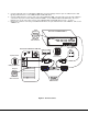
CASCADING CASCADING The UNIMUX-USBV-4O USB KVM switch can be expanded to access up to 128 CPUs by cascading multiple units together. As many switches as there are CPU ports may be connected to a UNIMUX-USBV-4O USB KVM switch. Single user and multi-user UNIMUX switches may be connected downstream (see Figs.16 and 17). The first switch in a cascaded system is referred to as the "master", while all downstream switches are referred to as "slaves".
Limitations The front panel buttons are only used to operate standalone switches. To control a cascaded network of switches, only the OSD commands within Command Mode will be recognized. Users connected to accessible ports on downstream slaves (i.e. ports not connected to the master, as in the case of multi-user slaves) will not be able to control switches or CPUs connected upstream. Only control over CPUs and slaves downstream from a user's connection point will be enabled. (See Fig.
R E A R N T I V IE W O F M A S T E R N E T W O R K T E C H N O L O G IE S IN C O R P O R A T E D R V ID E O 4 V ID E O U S E R 4 U S E R U S E R 3 2 3 V ID E O C P U 5 V D C 2 A - U N IM U X -U S B V -4 O 1 2 7 5 D a n n e r D r iv e , A u r o r a O h io 4 4 2 0 2 4 3 3 0 -5 6 2 -7 0 7 0 2 C P U w w w .n ti1 .
All the downstream switches should be powered ON before pressing any keyboard key. If there are USB extenders connected, they should also be powered ON. An extra time of about 5 seconds after powering-ON the last unit may be needed to complete the USB enumeration process. If the switch is a standalone unit (no downstream switches connected), the keyboard key could be pressed immediately. When a keyboard key is pressed, the master switch will start the process of detecting the configuration.
TROUBLESHOOTING TROUBLESHOOTING 1. 2. Verify all cables are securely connected and that the installation procedure was carefully followed.