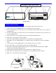
NTI R 1275 Danner Dr Tel:330-562-7070 NETWORK TECHNOLOGIES Aurora, OH 44202 Fax:330-562-1999 www.nti1.com INCORPORATED XTENDEXTM Series VOPEX-C5SVA/C5SV-x S-Video/Audio or S-Video Only Splitter/Extender Installation and Operation Manual (Receiver not included) Manual 054 Rev.
WARRANTY INFORMATION The warranty period on this product (parts and labor) is one (1) year from the date of purchase. Please contact Network Technologies Inc at (800) 742-8324 (800-RGB-TECH) or (330) 562-7070 or visit our website at http://www.nti1.com for information regarding repairs and/or returns. A return authorization number is required for all repairs/returns. COPYRIGHT Copyright © 2003 by Network Technologies Inc, all rights reserved.
Table of Contents Introduction.............................................................................................................................................................. 1 Materials .................................................................................................................................................................. 1 Features and Functions............................................................................................................................
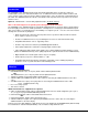
Introduction Introduction The XTENDEX Series VOPEX-C5SVA-x Cat5 Video/Audio Splitter/Extender is designed to enable one S-Video/Audio source to be viewed and heard in 4, 8, or 16 different remote locations. Remote monitors and stereo speakers can be located as much as 600 feet away from the source via Category 5 unshielded twistedpair cable. The VOPEX-C5SVA-x also allows a local monitor and self-powered stereo speakers to be located near the source.
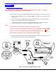
8 F E A T U R E S A N D 7 6 F U N C T IO N S 5 2 1 S -V o u t N T I N T I R N e t w o r k T e c h n o lo g ie s In c X T E N D E X T M V - V id e o A d ju s t 5 V D C 2 A R N E T W O R K T E C H N O L O G IE S IN C O R P O R A T E D S -V in 1 2 7 5 D a n n e r D r T e l:3 3 0 -5 6 2 -7 0 7 0 A u ro ra , O H 4 4 2 0 2 F a x :3 3 0 -5 6 2 -1 9 9 9 w w w .n ti1 .
Limitations Limitations • The audio input of the VOPEX-C5SVA-x S-Video/Audio Splitter/Extender is compatible with the following standard CPU audio outputs: • Line out - typically lime green in color • Speaker out- typically orange in color • Headphone out- typically located on the CD-ROM • The audio outputs of the VOPEX-C5SVA-x Video/Audio Splitter/Extender and the ST-C5SVA-R-600 Receiver are compatible with self-powered stereo speakers.
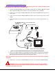
Installation Installation VOPEX-C5SVA-x and VOPEX-C5SV-x Note: VOPEX-C5SV-x S-Video Only Splitter/Extender does not have audio support. support is not present, please disregard all audio references. If the audio 1. Make connections between the VOPEX-C5SVA-x and the audio and video source(s). (See Fig. 1.) a) Connect a 4-pin miniDIN cable end of a SVEXT-6-MM to the VGA connector on the back of the video source.
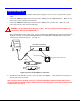
2. Connect the local user to the VOPEX-C5SVA-x (see Fig. 2) a. Connect one end of another SVEXT-xx-MM cable to the 4-pin miniDIN female connector marked "S-Vout" on the VOPEX-C5SVA-x. b. Connect the other end of the SVEXT-xx-MM cable to the 4-pin miniDIN female connector on the local s-video display. c. Connect the cable from the local speakers into the 3.5mm stereo audio connector marked "Line Out" on the VOPEX-C5SVA-x.
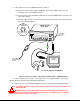
ST-C5SVA-R-600 and ST-C5SV-R-600 Receiver Note: This section is applicable to both models of Receiver except for step 4. When installing ST-C5SVR-600 Receivers (no audio support), disregard step 4. 1. Position a ST-C5SVA-R-600 Receiver such that the CAT5 cable, the SVEXT-xx-MM cable, speaker cable, and the AC adapter power connector can each reach the Receiver comfortably. 2. Connect one end of another SVEXT-xx-MM cable to the female 4-pin miniDIN video connector on the Receiver. 3.
Plug-in and and Power Power Up up Plug-in 1. Plug the power cord from each monitor and the power supply for each set of stereo speakers into a power outlet. 2. Connect the 5VDC AC adapter power connector to the 5VDC port on the VOPEX-C5SVA-x. Make sure the power connector goes into the port all the way. 3. Connect the 9VDC AC adapter power connector to the 9VDC port on each Receiver. Make sure each power connector goes into each port all the way. ! WARNING: The AC adapter for the Receiver is 9VDC.
VideoQuality Quality Video Video Quality Adjustment for VOPEX-C5SVA-x When powering ON the VOPEX-C5SVA-x, video quality adjustment is done automatically to assure the image is as clear as possible. Once the VOPEX-C5SVA-x is up and running, the video quality can be re-adjusted at any time by pressing the recessed 'Video Adjustment' button. (See Fig 5). Using the tip of a pen or pencil, a momentary press of the button will force the system to automatically re-adjust the video quality.
Side view of ST-C5SV-600 Receiver Press using pen or other pointed object to improve screen image Figure 6- Video quality adjustment buttons on ST-C5SV-600 Receiver Technical Specifications Maximum Resolution (refresh frequency 60Hz) Video Compatibility Video Quality Adjustment (VOPEX-C5SVA only) Video Coupling Video Connectors Video Maximum I/O Levels Input / Output Impedance Audio Connectors Signal Type Audio Frequency Response Signal-to-noise ratio Total Harmonic Distortion and Noise Stereo Crosstalk
Interconnection Cable Cable Wiring Wiring Method Method Interconnection The connection cable between the VOPEX-C5SVA-x and each ST-C5SVA-R-600 Receiver is terminated with RJ45 connectors and must be wired according to the EIA/TIA 568B industry standard. Wiring is as per the table and drawing below.
Problem Cause Solution Video picture is not sharp or is smeared • • • • • • • The picture on the monitor is black and white, rather than color A constant vertical wobble appears down the screen Display sometimes loses sync, causing it to go blank for a second or two No audio All Video Cables are not firmly seated. CAT5 cable is too long. The CAT5 cable is not properly connected. A cabling change has been made while the system was powered.