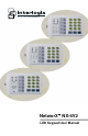
NetworX NX-6V2 LED Keypad User Manual
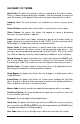
POWER Light is “on” w hen AC pow er is present; flashes to indicate a low battery condition. READY Light is “on” w hen the system is ready to arm; flashes if ready to “force arm”. SERVICE Light is “on” to indicate a trouble condition w ith your system. NX-6V2 SYSTEM KEYPAD Includes models NX-108E, NX-116E, NX-124E ARMED Light is “on” w hen armed; “off” w hen disarmed; flashes to indicate a previous alarm. INSTANT Light is “on” w hen there is no entry/exit delay.
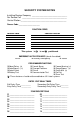
SECURITY SYSTEM NOTES Installing/Service Company _________________________________ For Service Call __________________________________________ Central Station ___________________________________________ Duress Code ____________________ FUNCTION CODES Function Code Controls Function This system is is not partitioned.
THIS MANUAL IS FURNISHED TO HELP YOU UNDERSTAND YOUR SECURITY SYSTEM AND BECOME PROFICIENT IN ITS OPERATION. ALL USERS OF YOUR SECURITY SYSTEM SHOULD READ AND FOLLOW THE INSTRUCTIONS AND PRECAUTIONS IN THIS BOOKLET. FAILURE TO DO SO COULD RESULT IN THE SECURITY SYSTEM NOT WORKING PROPERLY. THIS BOOKLET SHOULD BE KEPT IN AN ACCESSIBLE LOCATION FOR THE LIFE OF THE SECURITY SYSTEM. IF YOU DO NOT UNDERSTAND ANY PART OF THIS MANUAL YOU SHOULD NOTIFY YOUR INSTALLING COMPANY.
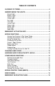
TABLE OF CONTENTS GLOSSARY OF TERMS ......................................................................4 UNDERSTANDING THE LIGHTS..........................................................5 Armed Light ..................................................................................5 Bypass Light.................................................................................5 Cancel Light..................................................................................5 Chime Light .....................
GLOSSARY OF TERMS Abort Delay: An option that allows a delay in reporting to the central station. There is a communicator delay of 30 seconds. It can be removed, or increased up to 45 seconds at the option of the end user by consulting with the installer. Authority Level: The level of access an individual has when using an alarm panel. Central Station: Location where alarm data is sent during an alarm report.
UNDERSTANDING THE LIGHTS Armed Light The armed light is “on” when the system is armed. The armed light is “off” when it is disarmed. The armed light will flash when there has been an alarm during the previous arm cycle. Bypass Light The b ypass light is “on” when any zone in this keypad’s partition is bypassed. The zone(s) that is bypassed will also be illuminated. If the b ypass light is “off”, no zones are bypassed. Cancel Light The cancel light will flash during an abort delay time.
Ready Light The ready light is “on” when the system is ready to arm and “flashes” if ready to force arm. The ready light is off when the system is not ready to arm because of a zone(s) being faulted. Stay Light The stay light is “on” when the all interior (motion detector) zones are bypassed. Zone Light The zone lights are “off” when everything is normal. A zone light will be “on” if the zone has been bypassed. If a zone light is “flashing”, that zone is in alarm or has been faulted.
KEYPAD FUNCTIONS ARMING YOUR SYSTEM IN THE “AWAY” MODE AWAY is used when the user is away from the premise and wants the interior protected. Listed below are the steps to arm in the AWAY Mode: Step 1 Step 2 Close all protected doors and windows. Ready light will be on or flashing when all prote cted zones and sensors are secure. NOTE: If any zones are bypassed, a sensor in that zone can be violated without affecting the ready light.
Step 3 Press the [STAY] key. The stay light will illuminate indicating that all interior zone s are bypassed. (All interior devices will bypass automatically, giving the user freedom of movement within the interior area.) The b ypass light will illuminate if any zone(s) are bypassed. If any zone(s) have been bypassed previously by the user, the light(s) corresponding to the bypassed zone(s) will illuminate, ale rting the user that a zone(s) may be unprotected and can be faulted without an alarm.
CANCEL / ABORT FEATURE (Optional, see page 1) The cancel light will flash during an abort delay time. If a code is entered followed by the [CANCEL] key while this light is flas hing, all abortable reports will stop the communication process. Entering a code followed by the [CANCEL] key during or after an alarm report to the central station will cause the cancel light to come on. It will stay on until the central station has recei ved the cancel report. No additional keypad tones will be emitted.
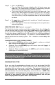
CHANGING USER CODES Step 1 Your system must be in the Disarmed state to change user codes. Step 2 Press []-[5]. Step 3 Enter a “Master Arm/Disarm Code”. NOTE: For partitioned systems, someone changing the code of another person must have access to all or more partitions than the user being changed. Step 4 The ready light will flash. Step 5 Enter the 2-digit “user number”. You must always enter 2 digits, such as [0] - [3] for user 3, or [1] - [2] for user 12.
LIGHT 1 2 3 4 5 6 7 8 AUTHORITY LEVELS IF LIGHT 8 IS OFF Reserved (Note: Do not change if on.) Arm Only Arm Only After Clos ing Time Master Arm/Disarm (can program other codes) Arm/Disarm Bypass Zones Open / Close Reporting If this light is on, this code is programmed as a function code. Do not change! Press [#] - [#] to exit. Step 6 Press the [ ] key. The ready light will flash. This moves you to the partition enable. (The user has access in partitions that are illuminated.
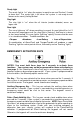
OTHER KEYPAD FUNCTIONS SETTING THE KEYPAD TONE Step 1 Press [ ]-[0]. Keypad is now in the “Adjust Tone” mode. Step 2 Pressing the [1] key will make the keypad sounder go to higher tones, pressing the [2] key will make the keypad sounder go to lower tones. Step 3 When the desired tone is reached, press the [#] key to set this tone and exit from the “Adjust Tone” mode. CHANGE PARTITION – Optional Step 1 Press [ ]-[1]. Step 2 Press a NUMBER key (1 or 2) to change partitions momentarily.
zone(s) will be displayed on the LCD keypad. entered into alarm memory and the internal log. It will also be Step 3 The keypad will begin to beep after 15 minutes in this mode. This beeping indicates that the “Walk-Test” mode will be automatically exited in 5 minutes. Step 4 To exit at any time during this mode, enter a user code. Otherwise the AWalk-Test Mode@ will automatically exit after 20 minutes. RESET FUNCTION This function is used to reset Smoke Detectors, Zone Troubles, and Zone Tampers.
Time Hour Code Time Hour Code Time Hour Code 12:00 Midnight 00 8:00 AM 08 4:00 PM 16 1:00 AM 01 9:00 AM 09 5:00 PM 17 2:00 AM 02 10:00 AM 10 6:00 PM 18 3:00 AM 03 11 7:00 PM 19 4:00 AM 04 12 8:00 PM 20 5:00 AM 05 11:00 AM 12:00 Noon 1:00 PM 13 9:00 PM 21 6:00 AM 06 2:00 PM 14 10:00 PM 22 7:00 AM 07 3:00 PM 15 11:00 PM 23 KEYPAD CONTROL TONES (BEEPS) A sounder is built into the keypad.
SERVICE MENU The service light will be “on” if the s ecurity system requires service. If the service light is “on”, press the [ ] key followed by the [2] key to determine the service condition. One or more zone lights will illuminate indicating what service(s) is required. Call your service provider immed iately for these problems. Below is a listing of what each light means in a service condition. LIGHT 1 PROBLEM SYSTEM FAULT - Press the [1] key.
EMERGENCY EVACUATION PLANS An emergency evacuation plan should be established for an actual fire alarm condition. For example, the following steps are recommended by the National Fire Protection Association and can be used as a guide in establishing an evacuation plan for your building. Draw up a floor plan of your home. Show windows, doors, stairs, and rooftops that can be used for escape. Indicate each occupant's escape routes. Always keep these routes free from obstruction.
SYSTEM NOTES 17
© 2012 UTC Fire & Security Americas Corporation, Inc. Interlogix is part of UTC Climate Controls & Security, a unit of United Technologies Corporation. All rights reserved.