
User manual


• a) Door
The dimensions of the door should be:
- width 595-598 mm
- thickness 16-22 mm
The height (C-Fig. C) depends on the height of the
adjacent furniture's base.
• b) Hinges
To mount the hinges it is necessary to drill two holes
(dia. 35 mm, depth 12.5-14 mm depending on the
depth of door furniture) on the inner side of the door.
The distance between the holes hobs fixing centres
must be 416 mm.
The distance (B) from upper edge of the door to the
centre of the hole depends on the adjacent furni-
ture's dimensions.
The required dimensions are given in the picture C.
The hinges will be fixed to the door by means of
screws for wood (2-Fig. B) supplied with the appli-
ance.
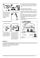
• c) Mounting the door
Fix the hinges (1) to the machine by means of the M
5x15 screws (3-Fig. B). The hinges can be adjusted
to compensate for possible uneven thickness of the
door.
To align the door perfectly it is necessary to loosen
the screw (3-Fig. B), adjust the door and tighten the
screw again.
D
4
6
8
Caution! Do not remove the screw 8!
d) Counter-magnet (6)
The appliance is prearranged for a magnetic closure
of the door.
To enable a correct operation of this device, it is nec-
essary to screw the counter-magnet (6) (steel disk +
rubber ring) into the inner side of the door. Its posi-
tion must correspond to the magnet (4) on the appli-
ance (see picture D).
E
1
2
3
7
5
6
4
8
Caution! Do not remove the screw 8!
If the door has to be opened from left to right, invert
the position of the plates (7), the magnet (4) and the
plate (5) (Fig. B and E). Mount the counter-magnet
(6) and the hinges (1) as previously described.
Recommendations regarding the construction
and fitting of a base when the installation re-
quires an integrated appliance to be raised.
Graphic F
Front view
5 mm Hardwood strip
Additional pieces
of timber should run
from front to back
40
600-605
100
23