KH 80 DSP Instruction Manual georg neumann gmbh · Leipziger str. 112 · 10117 berlin · germany tel +49 (0)30 / 41 77 24-0 · fax -50 · headoffice@neumann.com · www.neumann.com Publ.
Contents The KH 80 DSP studio monitor . . . . . . . . . . . . . . . . . . . . . . . . . . . . . . . . . . . . . . . . . . . . . . . 3 Delivery includes . . . . . . . . . . . . . . . . . . . . . . . . . . . . . . . . . . . . . . . . . . . . . . . . . . . . . . . . . . . 3 About this manual . . . . . . . . . . . . . . . . . . . . . . . . . . . . . . . . . . . . . . . .
The KH 80 DSP studio monitor Thank you for purchasing a Neumann studio monitor. The KH 80 DSP features a Mathematically Modeled Dispersion™ Waveguide (MMD™), DSP acoustical controls, control via standard IP networks and an extensive range of mounting hardware. This allows the loudspeaker to be used in diverse acoustical conditions, with any source equipment and in a wide variety of physical locations.
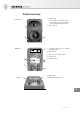
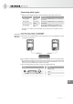
Product overview 1 Neumann logo • for information on the functionality of the Neumann logo refer to chapter “Functionality of the Neumann logo” Front panel 2 Bass reflex ports 1 2 2 Back panel 7 3 Threaded inserts (M6) for Neumann mounting hardware 4 On/off switch 5 RJ-45 socket for network control 6 Cooling vents 7 Control switches 3 6 4 5 Bottom 9 8 8 Mains socket 9 XLR/Jack analog input socket EN KH 80 DSP | 4
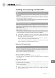
Installing and connecting the KH 80 DSP CAUTION Danger of injury and material damage due to tipping/dropping of the product! If improperly mounted, the product and/or the mounting hardware (e.g. rack) can tip over or drop down. XX Always have the product mounted by a qualified specialist according to local, national and international regulations and standards. XX Use the mounting systems recommended by Neumann and always provide sufficient additional protection against tipping or dropping.
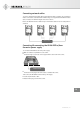
Positioning the loudspeakers XX Carry out the following steps very accurately, since the more accurate the physical arrangement of the loudspeakers in the room, the more accurate the reproduction will be at the listening position. Distances XX Observe the recommended distances between the loudspeakers and your listening position (imperial dimensions are approximate): • Minimum: 0.50 m (2') • Recommended: 0.8–1.75 m (2'6"–6') • Maximum: 3.
Connecting audio signals XX Always use good quality cables to achieve the maximum cable lengths shown below: Signal (connector) Cable length Connection Analog (XLR) up to 100 m (300’) directly to the ANALOG INPUT socket (XLR/Jack) (see below) Analog (Jack) up to 100 m (300’) directly to the ANALOG INPUT socket (XLR/Jack) (see below) Analog (RCA) up to 10 m (30') via an adapter (RCA-XLR or Jack-XLR) to the ANALOG INPUT socket (XLR/Jack) (see below) If possible, use a balanced connection (XLR, s
Connecting network cables To use the extended functionality offered by the Neumann.Control software, the loudspeaker must be connected to a standard network switch using a user supplied standard Ethernet cable (Cat 5 or better). The maximum length of the cable is 100 m. Refer to the Neumann.Control software help for information about how to use loudspeakers in a network.
Configuring and using the KH 80 DSP Switching the KH 80 DSP on/off On/Off XX Set the on/off switch to: • “ON” to switch on the loudspeaker. The Neumann logo lights up solid red while the DSP system boots up. After approximately 5 seconds it turns white indicating the loudspeaker is ready to be used. If the logo brightness has been set to less than 100% in the Neumann.Control software, it will be dimmed or off after the bootup phase is complete. • “OFF” to switch off the loudspeaker.
Functionality of the Neumann logo Action Logo indication Firmware activities Loudspeaker is booting up Solid red Loudspeaker boot up error Fast red flashing Loudspeaker firmware is being updated Solid rosé Loudspeaker resetting to factory default settings Rosé flutter flash Everyday operation Operating normally (dimmable via Neumann. Control) Solid white Loudspeaker in active system is solo’ed in Neumann.
SETTINGS switch The SETTINGS switch has two functions which can be turned on or off independently. STANDBY If the SETTINGS switch has been set to one of the two AUTO STANDBY = ON positions, the KH 80 DSP will switch to standby after 90 minutes. Standby means that the network interface, signal processing circuitry and power amplifiers are all powered down. Standby mode is automatically deactivated when a sufficiently large audio signal is detected at the analog input.
Adjusting the frequency response using the backpanel controls When the LOW MID control is set to FREE STANDING or, via the Neumann.Control software, the acoustical controls have been set to 0 dB, the KH 80 DSP loudspeaker is designed to have a flat frequency response in anechoic conditions. When the loudspeaker is installed in your monitoring environment, the response changes. The same loudspeaker installed in different positions in the same room may require different acoustical control settings.
Cleaning and maintaining the KH 80 DSP CAUTION Damage to the product caused by liquids! Liquids entering the product can cause a short-circuit in the electronics and damage or even destroy the product. XX Keep XX Before XX Use all liquids away from the product! cleaning, disconnect the product from the mains power supply. a soft, dry, and lint-free cloth to clean the product.
In compliance with Europe EMC EN 55032, EN 55103-2, Electromagnetic Environment: Class E3 Safety EN 60065, EN 62368-1 RoHS EN 50581 USA 47 CFR 15 subpart B Canada CAN ICES-3 (B)/NMB-3(B) Acoustical measurements and block diagram Additional technical data such as acoustical measurements and a block diagram can be found on the product page of the KH 80 DSP at www.neumann.com.
1 2 0° 1 1 0° 1 00° 90° 60° 30° 1 50° 22.5° 0° 1 80° 1 50° 22.