
User Manual


4 5
U87Ai
braiding as shield. It has a 5/8"-27 female thread,
plus a thread adapter to connect to 1/2"- and 3/8"
stands. Ø 5 mm, length 10 m. XLR 3 connectors.
AC 22 (0.3 m) ......................... Cat. No. 06598
Adapter cable with XLR 5 M connector and unbal-
anced 3.5 mm stereo jack. It is used to connect the
5-pin XLR output of the BS 48 i-2 power supply or
the MTX 191 A matrix amplifier to units with a
3.5 mm stereo input. It is designed for all micro-
phones of the fet 80/100 series and KM 100 F, ex-
cluding the KM 100 and the GFM 132.
AC 25 (0.3 m) ......................... Cat. No. 06600
Adapter cable with XLR 3 M connector and unbal-
anced 6.3 mm mono jack. It is used to connect
3-pin XLR outputs of power supplies to units with
a 6.3 mm monojack input. Designed for all micro-
phones, excluding KM 100 System and GFM 132.
AC 27 (0.3 m) ......................... Cat. No. 06602
Y-cable with XLR 5 M connector and two unbal-
anced 6.3 mm mono jacks. It is used to connect
XLR 5 outputs of the BS 48 i-2 power supply or the
MTX 191 A matrix amplifier to units with 6.3 mm
monojack inputs. Designed for all microphones,
excluding KM 100 System and GFM 132.
Custom-made cables are available on request.
4. Power Supply
4.1 Phantom Powering
The U 87 Ai microphone operates on 48 volt
phantom power (P48, IEC 1938).
With phantom powering the dc from the positive
supply terminal is divided via two identical resis-
tors, one half of the dc flowing through each au-
dio (modulation) conductor to the microphone, and
returning to the voltage source via the cable
shield. As a consequence, the effect of dc supply
voltage noise super-imposed on the microphone
output voltage is reduced by the common mode
rejection factor. Neumann microphones have a
common mode rejection factor exceeding 60 dB.
Phantom powering provides a fully compatible
connecting system, since no potential differences
exist between the two audio conductors. Studio
outlets so powered will therefore also accept dy-
2. Microphone Versions and
Output Wiring
These versions are available:
U 87 Ai ............... ni .............. Cat. No. 07022
Standard version with male 3-pole connector in-
sert and satin nickel finish. Requires XLR 3 F ca-
ble connector.
The microphone is wired as per DIN EN 60268-12
or IEC 60268-12:
Modulation is connected to pins 2 and 3, the shield
to pin 1. A sudden sound pressure rise in front of
the diaphragm causes a positive voltage to appear
at pin 2.
The U 87 Ai has an electrical source impedance of
200 ohms. The input impedance of the following
amplifier should be at least five times as great,
i.e. 1000 ohms.
U 87 Ai mt .......... blk ............. Cat. No. 07023
As above, but with matt black finish.
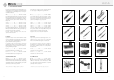
3. Microphone Cables
The cable length between microphone and follow-
ing preamplifier should not exceed 300 m
(980 ft.). The capacitance of greater cable lengths
could affect the frequency response and, in con-
junction with the leakage inductance of the micro-
phone’s output transformer, would result in a rise
at the upper end of the frequency range.
The following cables are available for the U 87 Ai
microphone:
IC 3 mt ................ blk ............. Cat. No. 06543
Microphone cable with double twist (double helix)
braiding as shield. Ø 5 mm, length 10 m. XLR 3
connectors, matte black.
IC 31 mt (5 m) .... blk ............. Cat. No. 06570
Microphone cable with double twist (double he-
lix) braiding as shield. Textile-braided to avoid
frictional noise due to the handling of booms or
plastic leadings (for example in windscreens).
Ø 4,5 mm, length 5 m. XLR 3 connectors, matte
black.
IC 4 (10 m) ......... ni ............... Cat. No. 06547
IC 4 mt (10m) .... blk ............. Cat. No. 06557
Microphone cable with rotatable swivel mount for
microphones with a thread, and double twist
2. Ausführungsformen und Beschaltung
des Ausganges
Folgende Ausführungsformen sind erhältlich:
U 87 Ai ............... ni ............. Best.-Nr. 07022
Standardausführung mit 3-poligem Switchcraft-
Steckereinsatz und nickelmatter Oberfläche. Erfor-
derliches Gegenstück: XLR 3 F.
Die Zuordnung der Mikrophonanschlüsse ent-
spricht DIN EN 60268-12 bzw. IEC 60268-12.
Die Modulationsadern liegen an Pin 2 und 3, die
Abschirmung an Pin 1. Bei einem Schalldruckan-
stieg vor der Mikrophonmembran tritt an Pin 2 eine
positive Spannung auf.
Das U 87 Ai hat einen elektrischen Innenwider-
stand von 200 Ohm. Der Eingangswiderstand des
nachfolgenden Verstärkers sollte möglichst fünf-
mal so groß oder größer sein, also 1000 Ohm.
U 87 Ai mt .......... sw ............ Best.-Nr. 07023
Wie oben, jedoch schwarzmatte Oberfläche.
3. Mikrophonkabel
Die höchste zulässige Kabellänge zwischen Mikro-
phon und Verstärker beträgt etwa 300 m. Bei grö-
ßeren Kabellängen beeinflusst die Kabelkapazität
den Frequenzgang und führt in Verbindung mit der
Streuinduktivität des Mikrophonübertragers zu-
nächst zu einem Anstieg am oberen Ende des Über-
tragungsbereiches.
Für das Mikrophon U 87 Ai stehen folgende Kabel
zur Verfügung:
IC 3 mt ............... sw ............ Best.-Nr. 06543
Mikrophonkabel mit Doppeldrallumspinnung als
Abschirmung. Ø 5 mm, Länge 10 m. XLR 3 Steck-
verbinder, schwarzmatt.
IC 31 mt (5 m) ... sw ............ Best.-Nr. 06570
Mikrophonkabel mit Doppeldrallumspinnung als
Abschirmung. Textilumsponnen, zur Vermeidung
von Reibgeräuschen bei der Verwendung an Mi-
krophonangel oder Windschutzkorb. Ø 4,5 mm,
Länge 5 m. XLR 3 Steckverbinder, schwarzmatt.
IC 4 (10 m) ........ ni ............. Best.-Nr. 06547
IC 4 mt (10 m) ... sw ............ Best.-Nr. 06557
Kabel mit dreh- und schwenkbarem Stativgelenk
für Mikrophone mit Gewindeanschluss, mit Dop-
peldrallumspinnung als Abschirmung. Der Gewin-
deanschluss hat 5/8"-27-Gang, mit Adapter für
1/2"- und 3/8"-Stative. Ø 5 mm, Länge 10 m.
XLR 3-Verbinder.
AC 22 (0,3 m) ...................... Best.-Nr. 06598
Adapterkabel mit XLR 5 F-Buchse und 3,5 mm Ste-
reoklinkenstecker, unsymmetrisch, für den An-
schluss des XLR 5-Ausganges des Speisegerätes
BS 48 i-2 oder der Matrixbox MTX 191 A an Gerä-
te mit 3,5 mm Stereoklinkenbuchse. Für alle Mikro-
phone außer der Ausgangsstufe KM 100 und des
GFM 132.
AC 25 (0,3 m) ...................... Best.-Nr. 06600
Adapterkabel mit XLR 3 F-Buchse und 6,3 mm Mo-
noklinkenstecker, unsymmetrisch, für den An-
schluss des 3-poligen XLR-Ausganges eines Spei-
segerätes an Geräte mit 6,3 mm Monoklinken-
buchse. Für alle Mikrophone mit Ausnahme der
Ausgangsstufe KM 100 und des GFM 132.
AC 27 (0,3 m) ...................... Best.-Nr. 06602
Y-Kabel mit einer XLR 5 F-Buchse und zwei 6,3 mm
Monoklinkensteckern, unsymmetrisch, für den An-
schluss des XLR 5-Ausganges des Speisegerätes
BS 48 i-2 oder der Matrixbox MTX 191 A an Gerä-
te mit 6,3 mm Monoklinkenbuchsen. Für alle Mi-
krophone mit Ausnahme von KM 100 und
GFM 132.
Andere Kabellängen sind auf Wunsch lieferbar.
4. Stromversorgung
4.1 Die Phantomspeisung
Das Mikrophon U 87 Ai wird mit 48 V phantomge-
speist (P48, IEC 1938).
Bei der Phantomspeisung fließt der Speisestrom
vom positiven Pol der Spannungsquelle über die
elektrische Mitte der beiden Modulationsadern
zum Mikrophon. Er wird hierzu über zwei gleich
große Widerstände beiden Tonadern gleichsinnig
zugeführt. Die Rückleitung des Gleichstroms erfolgt
über den Kabelschirm. Der Einfluss von Störspan-
nungen, die der Speisegleichspannung überlagert
sind, auf die Ausgangsspannung des Mikrophons
wird dadurch um das Maß der Unsymmetriedämp-
fung herabgesetzt, bei Neumann-Mikrophonen um
mehr als 60 dB. Mit der Phantomspeisung ist eine
kompatible Anschlusstechnik möglich, weil zwi-
schen beiden Modulationsadern keine Potential-