
User Manual


6 7
KMS 104/105
Die Zuordnung der Mikrophonanschlüsse und die
Polarität der Modulationsadern ist am Ausgang
des Speisegerätes die gleiche wie am Mikrophon.
Alle Anschlüsse mit XLR 3-Flanschdosen. Die Mo-
dulationsausgänge sind gleichspannungsfrei.
Das Gerät ist in drei Ausführungen erhältlich:
N 248 EU ............ sw ............ Best.-Nr. 08537
N 248 US ............ sw ............ Best.-Nr. 08538
N 248 UK ............ sw ............ Best.-Nr. 08539
6.3 Batteriespeisung
Steht keine Netzspannung zur Verfügung, kann die
Speisung mit einem der Geräte
BS 48 i .................................. Best.-Nr. 06494
(für ein Mikrophon)
BS 48 i-2 ............................... Best.-Nr. 06496
(für zwei Mikrophone)
erfolgen. Beide Geräte liefern 48 V ± 1 V, maximal
je 5 mA, und werden jeweils von einer 9 Volt-
Blockbatterie Typ IEC 6 F 22 gespeist.
Das Gerät BS 48 i-2 ist mit 5-poligen, das BS 48 i
mit 3-poligen XLR-Steckverbindern ausgerüstet.
(Siehe auch Neumann-Druckschrift 68832... „48 V-
Phantomspeisegeräte“).
Die Zuordnung der Mikrophonanschlüsse und die
Polarität der Modulationsadern ist am Ausgang der
Speisegeräte die gleiche wie am Mikrophon.
6.4 Betrieb an unsymmetrischen oder
mittengeerdeten Eingängen
Die 48 V-Phantom-Speisegeräte BS 48 i, BS 48 i-2
und N 248 haben gleichspannungsfreie Ausgänge,
so dass für den Anschluss an unsymmetrische Ein-
gänge kein Übertrager erforderlich ist.
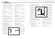
Beim KMS 104/105 ist
Pin 2 normgemäß die
„heiße Phase“. Für un-
symmetrische Eingänge
muss PIN 3 am Ausgang
des Speisegerätes an
Masse gelegt werden
(siehe Abbildung 1).
Bei vielen anderen als
den o.g. Phantomspeise-
geräten liegen nicht nur
die Modulationsleitun-
The assignment of the microphone terminals and
the modulation polarity at the power supply out-
put are identical to those at the microphone.
All connectors are of XLR 3 type. The audio signal
outputs are DC-free.
Three versions are available:
N 248 EU ............ blk ............. Cat. No. 08537
N 248 US ............ blk ............. Cat. No. 08538
N 248 UK ............ blk ............. Cat. No. 08539
6.3 Battery Powering
If a mains power source is not available, power
can be supplied by one of the battery units
BS 48 i .................................... Cat. No. 06494
(for one microphone)
BS 48 i-2 ................................. Cat. No. 06496
(for two microphones)
Both units deliver 48 V ± 1 V, at 5 mA maximum,
and are powered by a 9-volt monobloc battery
Type IEC 6 F 22.
The BS 48 i-2 is equipped with 5-pin XLR connec-
tors, the BS 48 i with 3-pin XLR connectors.
(See Neumann bulletin 68832... “Phantom 48 VDC
Power Supplies”.)
The assignment of the microphone terminals and
the modulation polarity at the power supply out-
put are identical to those at the microphone.
6.4 Operation with Unbalanced or
Center Tap
Grounded lnputs
The BS 48 i, BS 48 i-2 and N 248 phantom 48 Vdc
power supplies are dc-free so that no transformer
is required for connection to unbalanced inputs.
In the case of the
KMS 104/105 condenser
microphone pin 2 is the
“hot phase“, in accor-
dance with the standard,
and pin 3 of the output of
the power supply must
be connected to earth
(see Fig. 1).
In the case of many oth-
er phantom powering
units (except those men-
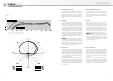
Abbildung / Figure 2
gen zum Mikrophon auf dem Potential der Speise-
spannung von +48 V, sondern auch die vom Spei-
segerät abgehenden Modulationsleitungen. Für
die in der Studiotechnik
allgemein üblichen sym-
metrischen und erdfreien
Verstärker und Mischpult-
eingänge ist dies ohne
Bedeutung. Dagegen wird
die Speisespannung beim
Anschluss an einseitig
oder mittengeerdete Ver-
stärkereingänge kurzge-
schlossen, und es ist kein
Betrieb möglich. Dann be-
stehen folgende Lösungs-
möglichkeiten:
a) In mittengeerdeten
Geräten mit Eingangs-
übertrager (z.B. einige
NAGRA-Geräte) kann die
betreffende Erdverbin-
dung fast immer ohne Nachteile für die Funktion
des Gerätes aufgetrennt werden.
b) In jede abgehende Modulationsleitung kann
zur Abblockung der 48 V-Gleichspannung eine RC-
Kombination eingefügt werden (siehe Abbildung 2
und Neumann-Information Nr. 84 221).
6.5 Betrieb an HF-Sendern
Die Solistenmikrophone können an Ansteck- oder
Taschensendern betrieben werden, die folgende
Vorraussetzungen erfüllen:
• Phantomspeisung 48 V, mind. 3,5 mA,
• Pin 2 signalführend („heiß“),
• ausreichender Dynamikbereich des Senders.
tioned above), not only the modulation leads to
the microphone, but also the outgoing modulation
leads from the powering unit, are at the potential
of the feed voltage
(+48 V). This is of no sig-
nificance for the bal-
anced, floating amplifier
and mixing console in-
puts in general studio
use. On the other hand,
the feed voltage will be
short-circuited when con-
nected to single-ended or
center tap grounded am-
plifier inputs, and no op-
eration will be possible.
This can be circumvented
as follows:
a) In center tap ground-
ed equipment with input
transformer (e.g. some
NAGRA units), the earth
lead can almost always be disconnected without
affecting the function of the equipment.
b) In every outgoing modulation lead, an RC net-
work can be incorporated to block the 48 Vdc
voltage (See Figure 2 and Neumann-Information
no. 84 222).
6.5 Operation with Wireless Transmitters
Both microphones can be operated with plug-on or
pocket transmitters fulfilling these specifications:
• P48 Phantom power, 3.5 mA min.,
• Signal on pin 2 (“hot”),
• sufficient dynamic range of the transmitter.
Abbildung / Figure 1