INSTRUCTION MANUAL NPPA-TT-IDC PATCH PANEL “Easy Patch” | 96 Bantam (TT) Jacks, IDC Termination NEUTRIK AG Liechtenstein Tel.: +423/237 24 24 Fax: +423/232 53 93 www.neutrik.com Draft. Nr.: Update: NEUTRIK Zürich AG Switzerland Tel.: +41 44/736 5010 Fax: +41 44/736 5011 NEUTRIK (UK) Ltd. NEUTRIK USA INC. Great Britain USA Tel.: +44 1983/811 441 Tel.: +1 732/901 9488 Fax: +44 1983/811 439 Fax: +1 732/901 9608 BDA98-1/ 3102M0881 03.08.2009 Data subject to change without prior notice. ©2007 NEUTRIK .
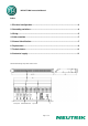
NPPA-TT-IDC Instruction Manual Index 1. Electrical configuration ............................................................................................3 2. Grounding variations ................................................................................................4 3. Wiring .........................................................................................................................5 4. Cable retention .............................................................................
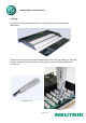
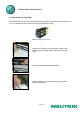
NPPA-TT-IDC Instruction Manual 1. Electrical configuration The Neutrik ”Easy Patch” Patch Panel is fitted with high quality, long life NJ3TTA gold plated double contact jacks (2 x 48). This Patch Panel is an innovative and compact patching system (just 1 U high) for 19” rack mounting. Robustly housed in black coated steel shell and featuring precision aluminum fittings it is built to last. The Neutrik "Easy Patch” is suitable for analog and digital audio signals.
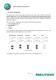
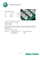
NPPA-TT-IDC Instruction Manual 2. Grounding variations The flexible grounding system provides the following versions. Individual: Each channel ground (“S” terminal) is connected to the dedicated ground conductor (drain wire) of the incoming cable shield, no connection between the solder pads. This is the standard configuration. Central: All channel grounds (individual Top and Bottom row) are connected via the Top and Bottom PCB bus by connecting the solder pads.
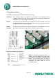
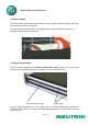
NPPA-TT-IDC Instruction Manual 3. Wiring For access to the terminals remove the top cover with three cross-recessed screws (M2.5x8mm). IDC-terminals with gas tight connection enable fast and easy wiring. No soldering or fixing with screws is necessary. For wiring please use the original LSA-tool from Krone (Product Nr.: 6417/1/810).
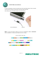
NPPA-TT-IDC Instruction Manual Color coding of terminals: white - sleeve (shield) red - tip (Signal +) black - ring (Signal -) The terminal handles solid cables AWG 26 to 20. Wire (conductor) diameter ≥ 0.40 mm ≤ 0.65 mm ≥ 0.65 mm ≤ 0.90 mm Wires per slot 2 1 When using wire in the range of 0.4 to 0.65mm diameter, the modules allow up to two identical wires of the same diameter to be terminated in one contact. It is not possible to use 2 wires of differing diameter.
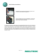
NPPA-TT-IDC Instruction Manual 4. Cable retention The built in cable retention bar is at the back at the casing. Simply attach the cables with cable ties to the bar as shown on the photo. For large and heavy bundles there is an additional strain relief bar NPPA-S available. It is attached to the casing with four screws. 5.
NPPA-TT-IDC Instruction Manual To write on the paper you have to unscrew one of the outer fixing screws of the front panel. Then pull out the side-stop, the transparent foil and the paper strip itself. After marking is done assemble the parts in reversed sequence. Remove labeling strip Side Stop NOTE: For easy and perfect marking you can use our designation software “PatchLabel” which is available on our web site www.neutrik.com free of charge.
NPPA-TT-IDC Instruction Manual 6. Replacement of Jack Pairs Each individual jack pair can be exchanged quickly and without fuss even while the panel is "on air". For replacement simply remove the easy accessible jack pairs. Module consisting of 2 Jack Pairs Remove Front Panel by unscrewing the 3 black crossrecessed screws (M3x8 Taptite), remove the two sidestops. Push out the channel identification strips.
NPPA-TT-IDC Instruction Manual Alternatively the jack pairs may be pulled out by the use of two Bantam plugs (diagonally plugged in). The two jack pairs have to be re-assembled in the right way so that the thicker body marked “left” is put on the left side with the mark outside and readable.
NPPA-TT-IDC Instruction Manual 7. Technical Data 7.1 Electrical Frequency range: Digital suitability: Channel separation: Insulation resistance: Connector contact resistance: Switch contact resistance: Dielectric strength: DC > 50 MHz Digital audio acc. to AES/EBU > 100 dB @ 10 kHz, 600 Ω terminated > 40 dB @ 6 MHz, 110 Ω terminated > 109 Ω @ 500 V dc < 20 mΩ < 25 mΩ 1000 V dc 7.