INSTRUCTION MANUAL NPPA-TT-S PATCH PANEL “Easy Patch” | 96 Bantam (TT) Jacks, Solder lugs NEUTRIK AG Liechtenstein Tel.: +423/237 24 24 Fax: +423/232 53 93 www.neutrik.com Draft. Nr.: Update: NEUTRIK Zürich AG Switzerland Tel.: +41 44/736 5010 Fax: +41 44/736 5011 NEUTRIK (UK) Ltd. NEUTRIK USA INC. Great Britain USA Tel.: +44 1983/811 441 Tel.: +1 732/901 9488 Fax: +44 1983/811 439 Fax: +1 732/901 9608 BDA84-1/ 3102M0821 03.08.2009 Data subject to change without prior notice. ©2007 NEUTRIK .
NPPA-TT-S Instruction Manual Index 1. Electrical configuration.................................................................................................3 2. Replacement of Jack Pairs ..........................................................................................4 3. Reconfiguration by hand..............................................................................................5 4. Grounding variations ...................................................................................
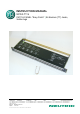
NPPA-TT-S Instruction Manual 1. Electrical configuration The Neutrik ”Easy Patch” Patch Panel is fitted with high quality, long life NJ3TTA gold plated double contact jacks (2 x 48). This Patch Panel is an innovative and compact patching system (just 1 U high) for 19” rack mounting. Robustly housed in black coated steel shell and featuring precision aluminum fittings it is built to last. The Neutrik "Easy Patch” is suitable for analog and digital audio signals.
NPPA-TT-S Instruction Manual 2. Replacement of Jack Pairs Each individual jack pair can be exchanged quickly and without fuss even while the panel is "on air". For replacement simply remove the easy accessible jack pairs. Module consisting of 2 Jack Pairs Remove Front Panel by unscrewing the 3 black cross-recessed screws (M3x8 Taptite), remove the two side-stops. Push out the channel identification strips.
NPPA-TT-S Instruction Manual The two jack pairs have to be re-assembled in the right way so that the thicker body marked “left” is put on the left side with the mark outside and readable. To complete, push the new jack pairs into the casing again with the mark on the left side (If more than one module are removed always assemble from the center to the right or left side and be careful that the keys on the left side of the jack pairs find their guiding slots.
NPPA-TT-S Instruction Manual Then remove the cover with a tiny grip at the side and carefully Pull out the configuration bars you need to exchange (preferably using a small screw-driver). Insert new bars carefully by pressing them in parallel at both ends. Attention: To ensure best contact conditions never reuse the configuration bars once being put in place! Always take new ones! Keep the contacts and switches in place with the thumb while manipulating the normalling contacts.
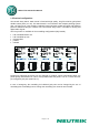
NPPA-TT-S Instruction Manual 4. Grounding variations The flexible grounding system provides the following versions: Individual: Group: Central: Chassis-Common: Each channel is individually grounded by its corresponding cable shield (default configuration). Selected channel grounds are connected via the ground bus on the PCB using solder bridges and track cuts to form a group that is connected to one common cable shield.
NPPA-TT-S Instruction Manual Grounding Variations NOTE: In standard configuration there is no ground connection between top and bottom row unless it is provided by an inserted patch cable.
NPPA-TT-S Instruction Manual Standard solder lugs enable a reliable and long-lasting wiring. Termination with solder lugs Solder bridges Solder tags 6. Cable retention to the unit The built in cable retention bar is at the back of the casing. Simply attach the cables with cable ties to the bar as shown in the photo. For large and heavy bundles there is an additional strain relief bar NPPA-S available. It is attached to the casing with four screws.
NPPA-TT-S Instruction Manual 7. Channel identification The front panel is equipped with channel identification strips located in the center of the channels and marked with the channel numbers 1-24 and 25-48 respectively. Channel identification strips Labeling strips For the perfect management of the system and for individual identification according to customer’s needs there are two large and separate labeling strips, one for the bottom and one for the top row.
NPPA-TT-S Instruction Manual Print-Out software “Patch Label” 8. Technical data 8.1 Electrical Frequency range Digital suitability Channel separation Insulation resistance Connector contact resistance Switch contact resistance Dielectric strength DC to > 50 MHz Digital audio acc. to AES/EBU > 100 dB @ 10 kHz, 600 Ω terminated > 40 dB @ 6 MHz, 110 Ω terminated > 109 Ω @ 500 V dc < 20 mΩ < 25 mΩ 1000 V dc 8.
NPPA-TT-S Instruction Manual 9.
NPPA-TT-S Instruction Manual 10.