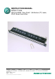
INSTRUCTION MANUAL NPPA-TT-E56 PATCH PANEL “Easy Patch” | 96 Bantam (TT) Jacks, EDAC 56-pin termination NEUTRIK AG Liechtenstein Tel.: +423/237 24 24 Fax: +423/232 53 93 www.neutrik.com Draft. Nr.: Update: NEUTRIK Zürich AG Switzerland Tel.: +41 44/736 5010 Fax: +41 44/736 5011 NEUTRIK (UK) Ltd. NEUTRIK USA INC. Great Britain USA Tel.: +44 1983/811 441 Tel.: +1 732/901 9488 Fax: +44 1983/811 439 Fax: +1 732/901 9608 BDA90-1/ 3102M0801 03.08.2009 Data subject to change without prior notice.
NPPA-TT-E56 Instruction Manual Index 1. Electrical configuration.................................................................................................3 2. Replacement of Jack Pairs ..........................................................................................4 3. Reconfiguration by hand..............................................................................................5 4. Grounding variations .................................................................................
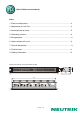
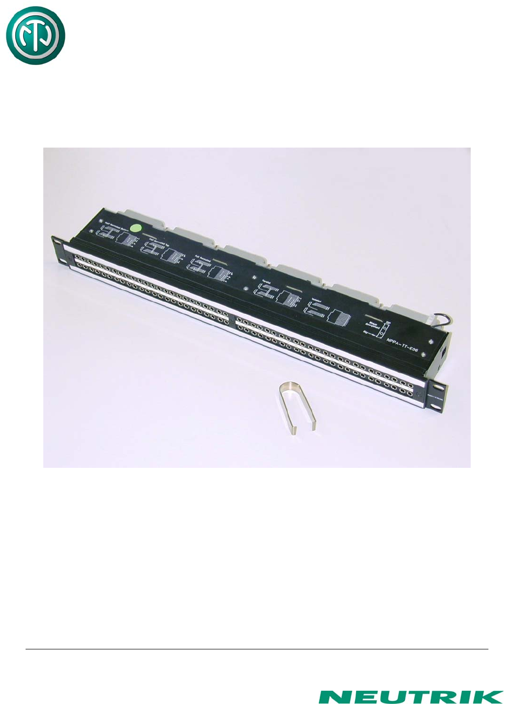
NPPA-TT-E56 Instruction Manual 1. Electrical configuration The Neutrik ”Easy Patch” Patch Panel is fitted with high quality, long life NJ3TTA gold plated double contact jacks (2 x 48). This Patch Panel is an innovative and compact patching system (just 1 U high) for 19” rack mounting. Robustly housed in black coated steel shell and featuring precision aluminum fittings it is built to last. The Neutrik "Easy Patch” is suitable for analog and digital audio signals.
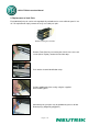
NPPA-TT-E56 Instruction Manual 2. Replacement of Jack Pairs Each individual jack pair can be exchanged quickly and without fuss even while the panel is "on air". For replacement simply remove the easy accessible jack pairs. Module consisting of 2 Jack Pairs Remove Front Panel by unscrewing the 3 black cross-recessed screws (M3x8 Taptite), remove the two side-stops. Push out the channel identification strips.
NPPA-TT-E56 Instruction Manual The two jack pairs have to be re-assembled in the right way so that the thicker body marked “left” is put on the left side with the mark outside and readable. To complete, push the new jack pairs into the casing again with the mark on the left side (If more than one module are removed always assemble from the center to the right or left side and be careful that the keys on the left side of the jack pairs find their guiding slots.
NPPA-TT-E56 Instruction Manual Then remove the cover with a tiny grip at the side and carefully Pull out the configuration bars you need to exchange (preferably using a small screw-driver). Insert new bars carefully by pressing them in parallel at both ends. Attention: To ensure best contact conditions never reuse the configuration bars once being put in place! Always take new ones! Keep the contacts and switches in place with the thumb while manipulating the normalling contacts.
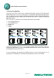
NPPA-TT-E56 Instruction Manual Symbolic structure of ground connection: S1 - S48 Corresponding flat tab for Top Row ground contacts S49 - S96 Corresponding flat tab for Bottom Row ground contacts Arrangement on PCB (seen from mating side) EDAC - key for orientation Flat tab to connect Ground cable Pin Header & Jumpers PCB Pin Header EDAC 56 pin Solder Pads to connect single ground contacts either to Common Top or Bottom ground-bus Configurations Chassis Top Chassis Bottom Chassis Common Note t
Female Header Page 8 of 12 Pin Header 2.
NPPA-TT-E56 Instruction Manual 6. Cable retention to the unit The ELCO®-EDAC® 56 connector is fixed to the housing by means of 4 screws. The plug itself is secured by one screw. The built in cable retention bar is at the back of the casing. Simply attach the cables with cable ties to the bar as shown in the photo. Cable Retention Bar 7.
NPPA-TT-E56 Instruction Manual To write on the paper you have to unscrew one of the outer fixing screws of the front panel. Then pull out the side-stop, the transparent foil and the paper strip itself. After marking is done assemble the parts in reversed sequence. Remove labeling strip Side Stop NOTE: For easy and perfect marking you can use our designation software “PatchLabel” which is available on our web site www.neutrik.com free of charge.
NPPA-TT-E56 Instruction Manual 8. Technical data 8.1 Electrical Frequency range: Digital suitability: Channel separation: Insulation resistance: Connector contact resistance: Switch contact resistance: Dielectric strength: DC to > 50 MHz Digital audio acc. to AES/EBU > 100 dB @ 10 kHz, 600 Ω terminated > 40 dB @ 6 MHz , 110 Ω terminated > 109 Ω @ 500 V dc < 20 mΩ < 25 mΩ 1000 V dc 7.
NPPA-TT-E56 Instruction Manual 9.