INSTRUCTION MANUAL NPP-TB PATCH PANEL “Easy Patch” | 48 TB Jack NEUTRIK AG Liechtenstein Tel.: +423/237 24 24 Fax: +423/232 53 93 www.neutrik.com Draft. Nr.: Update: NEUTRIK Zürich AG Switzerland Tel.: +41 44/736 5010 Fax: +41 44/736 5011 NEUTRIK (UK) Ltd. NEUTRIK USA INC. Great Britain USA Tel.: +44 1983/811 441 Tel.: +1 732/901 9488 Fax: +44 1983/811 439 Fax: +1 732/901 9608 NPP-TB 03.08.2009 Data subject to change without prior notice. ©2007 NEUTRIK . ALL RIGHTS RESERVED. NEUTRIK Tokyo Ltd.
NPP-TB Instruction Manual Index 1. Electrical configuration.................................................................................................3 2. Grounding Variations ...................................................................................................4 3. Wiring ..........................................................................................................................5 4. Cable retention to the unit................................................................
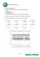
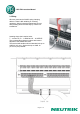
NPP-TB Instruction Manual 1. Electrical configuration The programming feature allows to set all switching configurations • • • • parallel half normalled top half normalled bottom and fully normalled ..... quickly and easily by jumper blocks individually for each channel. The delivery configuration for EASY PATCH NPP-TB is "Full Normalled".
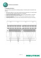
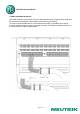
NPP-TB Instruction Manual 2. Grounding Variations There are several possibilities for individual grounding. The following items correspond to the drawing. 1. Standard grounding is to connect the ground terminals (marked with an "S") with the shield of the incoming cable, individual grounds are not connected. 2. Connecting the pads beside the numbers 1 - 24 with some solder leads to a connection between that channel and the common ground. 3.
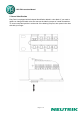
NPP-TB Instruction Manual 3. Wiring Wire are connected to WAGO spring clamping devices. There is NO soldering or screwing necessary. Simply insert the stripped wire (6 mm) after pressing down the white key by means of a screwdriver. Lettering above the insertion holes: T ... means TIP, R ... is RING and S ... is SLEEVE. The corresponding channel numbers are located adjacent to the WAGO terminals. The terminal will handle solid and stranded wire up to AWG 20 (0.5 mm²). Single wires up to AWG 18 (0.
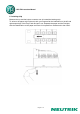
NPP-TB Instruction Manual 4. Cable retention to the unit The cable retention is at the back of the one piece metal housing. Simply put the cable onto the prismatic bar and attach it with cable ties as shown in the drawing. For large or thick bundles there is a rear extension bar (NPP-S) available as an option. It can be attached with four screws to the main housing. The cable is attached to the bar in the same manner as the standard version.
NPP-TB Instruction Manual 5. Cannel Identification Easy Patch is equipped with all channel identification labels in color black. If you need to replace or change the label colors first remove the label by means of a small screwdriver. To insert a new label position it at the side of the lettering strip first, then press in the other side with your finger.
NPP-TB Instruction Manual 6. Lettering strip Between the top and the bottom connector row is located the lettering strip. To write on the paper strip lift the strip with your fingernail at the indentation on the left and right respectively of the Easy Patch and pull it out. Separate the paper and the Plexiglas, write the identification on the paper and insert it into panel from outside end to the center.
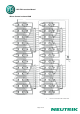
NPP-TB Instruction Manual Wiring diagram vertical PCB Page 9 of 11
NPP-TB Instruction Manual Wiring diagram horizontal PCB Page 10 of 11
NPP-TB Instruction Manual 7. Technical data Electrical Connector contact resistance: Insulation resistance: Cross talk between stereo pairs: Cross talk between two adjacent channels: Mechanical Jack lifetime: Insertion / Withdrawal force: Dimensions: < 10 mΩ / Switch contact resistance: < 15 mΩ > 109 Ω @ 500 VDC / Dielectric withstanding voltage: 1000 VDC acc. IEC 512-2 > 120 dB @ 1 kHz, 600 Ω terminated > 120 dB @ 1 kHz > 10.