INSTRUCTION MANUAL NPPA-TT-SD50 PATCH PANEL “Easy Patch” | 96 Bantam (TT) Jacks, 50 pin D-subminiature NEUTRIK AG Liechtenstein Tel.: +423/237 24 24 Fax: +423/232 53 93 www.neutrik.com Draft. Nr.: Update: NEUTRIK Zürich AG Switzerland Tel.: +41 44/736 5010 Fax: +41 44/736 5011 NEUTRIK (UK) Ltd. NEUTRIK USA INC. Great Britain USA Tel.: +44 1983/811 441 Tel.: +1 732/901 9488 Fax: +44 1983/811 439 Fax: +1 732/901 9608 BDA82-0 16.01.2009 Data subject to change without prior notice. ©2007 NEUTRIK .
NPPA-TT-SD50 Instruction Manual Index 1. Electrical configuration.................................................................................................3 2. Replacement of Jack Pairs ..........................................................................................4 3. Reconfiguration by hand..............................................................................................5 4. Grounding variations ................................................................................
NPPA-TT-SD50 Instruction Manual 1. Electrical configuration The Neutrik ”Easy Patch” is fitted with high quality, long life NJ3TTA double contact jacks (2 x 48) with drastically improved contact integrity. The NJ3TTA double contact jacks are gold plated and prewired. The Neutrik ”Easy Patch” is an innovative and compact patching system (just 1 U high) for 19” rack mounting. Robustly housed in black coated steel casing and featuring precision aluminum fittings it is built to last.
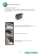
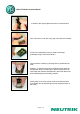
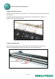
NPPA-TT-SD50 Instruction Manual 2. Replacement of Jack Pairs Each individual jack pair can be exchanged or re-configured without fuss even while the unit is “on air”. For replacement or re-configuration just remove the easy accessible module consisting of two “Plug-in Units”. Module consisting of 2 Jack Pairs Remove Front Panel by unscrewing the 3 black cross-recessed screws (M3x8 Taptite), remove the two side-stops. Push out the channel identification strips.
NPPA-TT-SD50 Instruction Manual Alternatively the jack pairs may be pulled out by the use of two Bantam plugs (diagonally plugged in). The two jack pairs have to be re-assembled in the right way so that the thicker body marked “left” is put on the left side with the mark outside and readable.
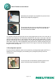
NPPA-TT-SD50 Instruction Manual ...to slide the jack pairs against each other in axial direction. Then remove the cover with a tiny grip at the side and carefully Pull out the configuration bars you need to exchange (preferably using a small screw-driver). Insert new bars carefully by pressing them in parallel at both ends.
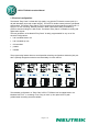
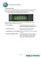
NPPA-TT-SD50 Instruction Manual 4. Grounding variations The patch panel is terminated with 4 Sub-D connectors each of them corresponding to groups (Sub-D groups) of 12 channels. Each Sub–D connector has only two ground contacts: • one for the top row connecting all top row ground contacts • one for the bottom row connecting all bottom row ground contacts Each Sub-D group is configured by its own jumper block.
NPPA-TT-SD50 Instruction Manual Jumper Setting Floating Grounding Variations Note: Phantom powered microphones In general it is not recommended to run phantom power through patch panels. In the case it is required to patch phantom powered microphones, all of the shields (SLEEVE contacts) from this device must be tied together. This can be accomplished by grouping the grounds of these channels via the PCB bus (using solder bridges). This group is then connected onto the general technical ground.
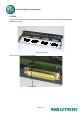
NPPA-TT-SD50 Instruction Manual 5. Wiring Four Sub-D connectors with 50 pins each enable fast and easy wiring even with the patch panel installed in the rack.
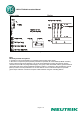
NPPA-TT-SD50 Instruction Manual 6. Cable retention to the unit The built in cable retention bar is at the back of the casing. Simply attach the cables with cable ties to the bar. For large and heavy bundles there is an additional strain relief bar NPPA-S available. It is attached to the casing with four screws. Cable retention bar 7.
NPPA-TT-SD50 Instruction Manual For the perfect management of the system and for individual identification according to customer’s needs there are two large and separate labeling strips, one for the bottom and one for the top row. To write on the paper you have to unscrew one of the outer fixing screws of the front panel. Then pull out the side-stop, the transparent foil and the paper strip itself. After marking is done assemble the parts in reversed sequence.
NPPA-TT-SD50 Instruction Manual 8. Technical data 8.1 Electrical Frequency range: Digital suitability: Channel separation: Insulation resistance: Connector contact resistance: Switch contact resistance: Dielectric strength: DC to > 50 MHz Digital audio acc. to AES/EBU > 100 dB @ 10 kHz, 600 Ω terminated > 40 dB @ 6 MHz, 110 Ω terminated > 10 GΩ @ 500 V dc < 20 mΩ < 25 mΩ 1000 V dc 8.
NPPA-TT-SD50 Instruction Manual 9.
NPPA-TT-SD50 Instruction Manual 10. Ordering Information 10.