
Instruction Manual
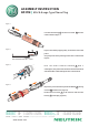

First slide the housing A and the strain relief B onto the
cable as shown in figure 1.
Prepare the cable by stripping away 12 mm of the outer cable
jacket.
Strip away 3 mm of the jacketing of each wire as indicated in
figure 2.
Heat the shield terminal labelled C with a
soldering bit, then position the shield on the heated terminal
and allow solder to melt affixing the wire to the terminal.
Repeat the process with the tip terminal labelled D and ring
terminal E with the wires (figure 3).
Position the strain relief F on the connector and tourn the
housing G on the plug (figure 4).
figure 1
figure 2
figure 4
figure 3
A
B
NEUTRIK
NP3TMC
12
3
Recommended cable OD: 6.2 mm
D
E
C
F
NEUTRIK
NP3TMC
G
NEUTRIK AG
NEUTRIK Zürich AG
NEUTRIK USA Inc.
NEUTRIK UK Ltd.
()
LI
CH
USA
UK
T: F:
T: F:
T: F:
T: F:
+423 / 237 24 24 +423 / 232 53 93
+41 44 / 736 5010 +41 44 / 736 5011
+1 732 / 901 9488 +1 732 / 901 9608
+44 1983 / 811 441 +44 1983 / 811 439
Draft. Nr.: Update: 28.09.20093102M0731
II
Data subject to change without prior notice. 2009 NEUTRIK . ALL RIGHTS RESERVED.©
®
NEUTRIK
NEUTRIK France
NEUTRIK Tokyo Ltd.
NEUTRIK
Vertriebs GmbH
Ltd.Hong Kong
DE / NL / AT
FR
JP
HK
T: F:
T: F:
T: F:
T: F:
+49 8131 / 280 890 +49 8131 / 280 830
+33 1 / 4131 6750 +33 1 / 4131 0511
+81 3 / 3663 4733 +81 3 / 3663 4796
+852 / 2687 6055 +852 / 2687 6052
ASSEMBLY INSTRUCTION
www.neutrik.com
NP3TM MIL/B-Gauge Type Phone Plug
|