Content 1 Scope ..................................................................................................................................................3 Theory ......................................................................................................................... 3 2 3 4 HD Video Formats ..............................................................................................................................3 2.
Especially the opportunity to reuse the existing infrastructure has been one of the critical success factors for SDI and is characterized by the ability of the interface to evolve over time, while retaining the use of the existing cable installation, patch panels, and BNC connectors. The so far latest step of evolution for the serial digital interface was the introduction of the 1080p/60 video image.
frequencies the impedance of BNC connectors became more important than ever. Every deviate impedance has a negative influence on the "return loss“ / "VSWR“ (Voltage Standing Wave Ratio) which are important measurements for reflected signals in a transmission line. Especially on high frequencies - as they occur when transmitting high frame rate HD signals (typical transmission @ 4.5 GHz) - an impedance mismatch results in a lot of return loss. 3.3 4.
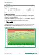
MEASUREMENTS 5 Return Loss 5.1 Measurement Setup Figure 3 5.2 Measurement Conditions Return loss measurement has been carried out with Neutrik NBNC75BTU11 75 Ω BNC connectors. To compare the results of the Neutrik connectors, we have chosen the BNC connectors of a European manufacturer (Standard series & HD optimized series), whose products are widely spread in broadcast applications across Europe, as reference.
5.4 Conclusion The cable assembly with the Neutrik rearTWIST® 75 Ω BNC Connectors offer at least 15 dB return loss budget with respect to SMPTE 424M requirements. This is a minimum of 7 dB more return loss budget compared to European manufactured products. To achieve this outstanding result every Neutrik BNC connector has been adapted to the measurements of a small group of cables, this guarantees the best possible performance and a minimized return loss.
6.3 Measurement Results 6.3.1 Neutrik NBNC75BTU11 with Belden 1694A coax cable a) b) DUT …8x DUT… DUT 42.1 ps/div 42.1 ps/div Figure 6 Figure 7 Connector type Timing jitter pk – pk [ps] [UI] DUT Rise time [ps] Fall time [ps] a) Neutrik NBNC75BTU11 34.47 0.10 126 112 b) Neutrik NBNC75BTU11 37.71 0.11 205 158 Adapter: Neutrik NBB75FG 6.3.2 European Manufacturer HD optimized product with Belden 1694A coax cable a) b) DUT …8x DUT… DUT 42.1 ps/div 42.
6.4 Conclusion As written in section 2.2, jitter cannot be eliminated completely. However, in order to reduce the potential jitter to a minimum, Neutrik concentrates on getting to the heart of the problem by optimizing connectors and its material. Transmission line Timing Jitter (Method b): Unit Interval (UI) 0.6 0.5 Neutrik NBNC75BTU11 0.4 0.3 European Manufacturer HD 0.2 European Manufacturer Standard 0.