
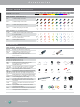
XLR Part Number Guide
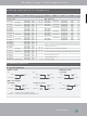

www.neutrik.com 39
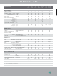
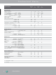
Accessories Technical Data
Number of contacts 3 - 5 3 3 - 5 3 3 - 7 3 3
Contact resistance
≤
6 mΩ
Insulation resistance - initial:
>
10 GΩ
- after damp heat test:
>
1 GΩ
Dielectric strength 1.5 kV dc
Rated voltage
<
50 V ac
Rated current per contact
3 pole: 6 A
16 A 1 A 16 A
4 pole: 6 A
- - 10 A - -
5, 6 pole: 3 A
-
- 7.5 A - -
7 pole: 5 A
- - - -
- -
Combo XLR + Jack contact 7.5 A
- - - - - - -
Capacitance between contacts -
3 pole:
≤
4 pF - ≤ 4 pF ≤ 4 pF ≤ 4 pF
4, 5, 6 pole:
≤
7 pF
- - - -
7 pole:
≤
9 pF - - - -
- -
Lifetime
>
1`000 mating cycles
Insertion / withdrawal force
≤
20 N
Retention method
- standard: latch lock
- "0" Version:
≥
20 N separating force
- -
Crimp XX: 0.22 - 0.34 mm
2
/ AWG 24 - 22 - - - - - -
1) : B Series 3 pole connectors > B-screw, 4 & 5 pole versions > A-screw
2)
: 4 + 5 pole A series, 5 pole B series
Operating temperature -30 °C to +80 °C
Protection class IP 40
Flammability UL 94 HB -
UL 94 V-0 3 pole - 3 pole - - -
Solderability complies with IEC 68-2-20
Mounting screw A A 1) - - - -
Color coding
ACR*
2)
- ACR*
2)
DSS DSS DSS DSS
(4 + 5 pole only)
Specification A AA B D DL / DLX DLX DLX-HE
Series Series Series Series Series Crimp Series
Electrical
Mechanical
Material
Environmental
Insert Polyamide PA 6.6 30% GR PSS 40% GR
Shell Zinc diecast ZnAI4Cu1
- - -
Shell plating gal Ni or black Cr
- -
velour Cr
Ring Zinc diecast ZnAI4Cu1
- - - - - -
Contacts - female 3 pole: Bronze CuSn6
4 – 5 pole: Bronze CuSn6
- - - - - -
4 – 7 pole: Brass CuZn39Pb3
- - - -
- -
- male: Brass CuZn35Pb2
Contact surface gal 0.2 µm AuCo over 2 µm NiP15 (Tribor
®
) - - -
gal 2 µm Ag or gal 0.2 µm Au hard alloy over 2 µm Ni - - - -
Latch lock & spring Ck 67 steel, treated