200/1400 and 1500 Treadmills Serial No: _______________________ Date of Purchase: ____________ Write the serial number in the space above for reference. OWNER’S MANUAL F OR M AXIMUM E FFECTIVENESS AND Serial Number Decal For Service or Parts call: 1-800-497-5831 S AFETY, P LEASE R EAD T HIS O WNER ’ S M ANUAL B EFORE U SING Y OUR N EW B ALANCE 1200/1400/1500 T READMILL .
TABLE OF CONTENTS Important Safety Instructions ...........................................................2 Introduction/Customer Service Information ..................................3 Unit Warning/Caution Labels and Specifications & Parts.........4-5 Assembly/Setup Instructions .......................................................6-10 Folding and Moving Your Treadmill for Storage .....................11-12 Taking Care of Your Treadmill ...................................................
IMPORTANT SAFETY INSTRUCTIONS Read all instructions before using this equipment. – THIS EQUIPMENT IS FOR CONSUMER USAGE ONLY – CAUTION: Exercise of a strenuous nature, as is customarily done on this equipment, should not be undertaken without first consulting a physician. No specific health claims are made or implied as they relate to the equipment.
INTRODUCTION CONGRATULATIONS ON PURCHASING YOUR NEW BALANCE TREADMILL With this product in your home, you have everything you need to start your own workout program to tone and firm the major muscle groups of your lower body. This is vital for all of us, regardless of age, sex, or fitness level, and regardless of whether your primary goal is toning, health maintenance, or more energy for daily activities.
UNIT WARNING/CAUTION LABELS AND SPECIFICATIONS & PARTS Important: See below for placement of the following warning/caution labels on your Treadmill. WARNING LABEL 1 WARNING LABEL 2 WARNING WARNING FAILURE TO READ AND FOLLOW THE SAFETY INSTRUCTIONS STATED IN THE OWNER’S MANUAL MAY RESULT IN POSSIBLE SERIOUS INJURY OR DEATH. KEEP CHILDREN AWAY. MAXIMUM USER WEIGHT 275/300 LBS. REPLACE THIS LABEL IF DAMAGED, ILLEGIBLE OR REMOVED. CLASS HC. RISK OF ELECTRICAL SHOCK.
WARNING LABEL 4 WARNING CRUSH HAZARD. KEEP HANDS AND FEET CLEAR DURING FOLDING. FAILURE TO DO SO COULD RESULT IN CRUSHED HANDS AND FEET. WARNING LABEL 5 WARNING LABEL 5 safety switch on/off switch WARNING ALWAYS UNPLUG THE POWER CORD IMMEDIATELY AFTER USE. WARNING LABEL 4 power cord CAUTION LABEL 10 CAUTION WARNING LABEL 6 BEFORE FOLDING THE TREADMILL, DECREASE INCLINE TO "0" LEVEL. FAILURE TO DO SO MAY RESULT IN SERIOUS DAMAGE TO TREADMILL AND VOID WARRANTY.
ASSEMBLY/SETUP INSTRUCTIONS WARNING DO NOT MOVE TREADMILL OUT OF THE BOX UNTIL UNIT IS ASSEMBLED. COLLAPSE BOX BOTTOM AND LAY SIDES DOWN BEFORE ASSEMBLY. WHEN MOVING ASSEMBLED TREADMILL OUT OF THE BOX, MOVE IT OUT OF THE BOX ON ITS WHEELS WHILE THE DECK IS IN THE FOLDED AND LOCKED POSITION. For Maximum Effectiveness and Safety, Please Read This Owner’s Manual Before Assembling or Using Your New Balance 1200/1400/1500 Treadmill.
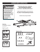
Note: We recommend setting up the unit in the area where it will be used. Remove Box Top. Collapse Box Bottom and leave unit in box to assemble. STEP 1 - Upright Assembly M8 curved washer a) Stand on Walking Belt and grip the uprights and slowly raise them into the assembled position. Secure the right side with (2) M8 x 20mm Allen Bolts (1) M8 Washer and (1) M8 Curved Washer at the bottom of the right Upright as shown in Figure 1. Repeat on other side. b) Use the Allen Wrench provided to tighten.
STEP 3 – Side Cap Assembly a) Attach Side Cap with (3) M4 x 6mm Phillips Screws at the bottom of the Upright. Repeat on other side. b) Use the Multi Hex Tool with Phillips Screwdriver provided to tighten. upright M4 x 6mm phillips screws Figure 3 - Install Side Caps side cap FOR 1500 UNITS ONLY STEP 4 – Adding Cup Holders to the Console Base Assembly Insert Cup Holders into the two holes provided. Please make sure the taller side of the Cup Holder is facing away from the Walking Belt.
SETTING UP TREADMILL FOR USE STEP 2 STEP 1 1200/1400 UNITS knob locking indicator Folding the Treadmill to allow removal of the shipping box. After assembly is complete, you must fold and move the Treadmill to remove the box. To fold the Treadmill, raise the Deck. Secure the Deck in the upright position by pushing the Knob in while rotating it clockwise until the Locking Indicator is fully visible.
STEP 3 Continued 1500 UNIT CAUTION TO REDUCE THE RISK OF DAMAGING ELECTRICAL PARTS TO YOUR TREADMILL, WE STRONGLY RECOMMEND THAT YOU PLUG YOUR TREADMILL INTO A DEDICATED 20 AMP OUTLET, WITHOUT THE USE OF AN ADDITIONAL EXTENSION CORD. PLEASE NOTE THAT THIS TREADMILL IS NOT COMPATIBLE WITH GFCI-EQUIPPED OUTLETS. IF YOUR TREADMILL HAS BEEN EXPOSED TO COLDER TEMPERATURES, WE RECOMMEND THAT THE TREADMILL IS WARMED UP TO ROOM TEMPERATURE BEFORE FIRST TIME USE. FAILURE TO DO SO MAY CAUSE ELECTRONIC FAILURE.
FOLDING AND MOVING YOUR TREADMILL FOR STORAGE 1200/1400 UNITS 1500 UNIT knob locking indicator TO FOLD THE TREADMILL TO FOLD THE TREADMILL You may fold the Treadmill into the upright position for storage. You may fold the Treadmill into the upright position for storage. CAUTION BEFORE FOLDING THE TREADMILL, DECREASE INCLINE TO "0" LEVEL. FAILURE TO DO SO MAY RESULT IN SERIOUS DAMAGE TO TREADMILL AND VOID WARRANTY. NOTE: Make sure the Treadmill's elevation is at the lowest position.
1200/1400 UNITS 1500 UNIT locking indicator not visable WARNING CRUSH HAZARD KEEP HANDS CLEAR OF DECK. FAILURE TO DO SO COULD RESULT IN CRUSHED HANDS. To Lower the Treadmill To Lower the Treadmill To lower the Deck, push in and turn the Knob counter-clockwise until the Locking Indicator is not visible and the Deck is released. NOTICE: This Treadmill has a built-in safety feature to help the Deck lower slowly when unfolding.
TAKING CARE OF YOUR TREADMILL WARNING: Always turn off and unplug the Treadmill from the electrical outlet before moving, cleaning, lubricating, or servicing the Treadmill. Note: The Treadmill MUST be placed on a level surface only. If the Treadmill is not level, the belt will continuously slip to the low side of the Treadmill. CAUTION: DO NOT USE Treadmill if it is not on a level surface. Have plenty of clearance behind and in front of your Treadmill.
WARNING: Always turn off and unplug the Treadmill from the electrical outlet before cleaning, lubricating, or servicing the Treadmill. CLEANING Keeping the Treadmill clean will prolong the life of the Treadmill and improve performance. WALKING BELT AND DECK LUBRICATION Your Treadmill Belt has been lubricated at the factory, but periodic lubrication will extend the life of your Treadmill Belt, Board, and Electrical Components.
1200 1400/1500 Electronics Operating Instructions For Your Treadmill SAFETY TIPS: • • • Practice mounting and dismounting your Treadmill before beginning your workout. Attach the Safety Key to the Computer (the Treadmill will not operate without the Safety Key). Clip the other end of the Safety Key to your clothing before exercising to ensure the Treadmill will stop if the user accidentally walks off the Treadmill.
16 Displays the preset or user programs. Also will display the elevation and elevation gain values for three seconds during workout. When power is off, press for 2 seconds to change from miles to kilometers. SELECT Increases or decreases the INCLINE when pressed. START/STOP KEY POWER KEY Pressing this confirms the selection of a program. Also confirms the speed and incline values during the setting of a user program. The Computer can be operated only with the Safety Key attached to the Treadmill.
1% Displays the preset or user programs. Also will display the elevation and elevation gain values for three seconds during workout. When power is off, press for 2 seconds to change from miles to kilometers. 3% 2% WALKING FAT BURN PIKES PEAK MTN. PASS HILL WALK PROGRAMS SELECT INCLINE + - ENTER ENTER SPEED HI + - START/STOP KEY SAFETY KEY FAN MPH 3 Pressing this key brings power to the Treadmill and must be pressed before any other key.
DISPLAY FUNCTION 1200 Please read carefully before using the Treadmill. INCLINE/PULSE: Displays pulse rate except when elevation is changed or SELECT key is pressed. To get a pulse rate, place both of your hands on the Pulse Grip Bars. It is recommended to straddle the Walking Belt to get an accurate reading. If you are walking or jogging, it is difficult for the Computer to accurately read your pulse rate. (See page 22 for more details.) TIME: Shows workout Time. Time begins at 00:00 and counts up.
1200 PROGRAMS MANUAL MODE: If you elect to operate the Treadmill in Manual Mode, press START. The Treadmill will start at 0.5mph after a 3,2,1 countdown. 4. Fat Burn: This is an interval elevation program where the elevation alternates between 0% and 5%. The user controls the speed. PROGRAM MODE: After pressing POWER, press the desired program using the program Quick Keys or press SELECT to choose one of the programs. Note: The program layout appears in the dot matrix display.
1400 1500 OPERATION INSTRUCTIONS Please read carefully before using the Treadmill. DISPLAYS INCLINE/PULSE: Displays pulse rate except when elevation is changed or SELECT key is pressed. To get a pulse rate, place both of your hands on the Pulse Grip Bars. It is recommended to straddle the Walking Belt to get an accurate reading. If you are walking or jogging, it is difficult for the Computer to accurately read your pulse rate. (See page 22 for more details.) TIME: Shows workout Time.
1400/1500 PROGRAMS MANUAL MODE: If you elect to operate the Treadmill in Manual Mode, press START. The Treadmill will start at 0.5mph after a 3,2,1 countdown. PROGRAM MODE: After pressing POWER, press the desired program using the program Quick Keys or press SELECT to choose one of the programs. Note: The program layout appears in the dot matrix display. Press ENTER to verify the selection. Press START to begin the program. All programs have ten segments.
1200 USING THE PULSE FUNCTION 1400/1500 The Pulse Window on your Computer works in conjunction with the Pulse Sensors found on the Console. When you are ready to read your pulse: 1. Place both hands firmly on the Pulse Sensors. For the most accurate reading, it is important to use both hands. 2. Look at your Pulse Window. The “P” will begin to blink. 3. Your estimated heart rate will appear in the window approximately 6 seconds after you grasp the Pulse Sensors. 4.
EXERCISE GUIDELINES IMPORTANT Please review this section before you begin exercising. IMPORTANT: If you are over 35 and have been inactive for several years, you should consult your physician, who may or may not recommend a graded exercise test. If you are just beginning your exercise program, your target heart rate range should be roughly at 60% of your maximum heart rate.
described previously. Each workout should begin with a warm up and end with a cool down. As a general rule, space your workouts throughout the week and avoid consecutive days of hard exercise. Here are the amounts of activity necessary for the average healthy person to maintain a minimum level of overall fitness. Included are some of the popular exercises for each category. WARM UP – 5 -10 minutes of exercise such as walking, slow jogging, knee lifts, arm circles or trunk rotations.
40 year old to get a cardiovascular effect the individual would need to keep their heart rate at or above 126 beats per minute to get a cardiovascular effect. Note: Although 70% was used in this example, the heart rate range needed to achieve results falls between 60% and 85% of your maximum heart rate. If you are just beginning your exercise program, your target heart rate range should be roughly at 60% of your maximum heart rate.
HEART RATE TARGET ZONE FOR CARDIOVASCULAR FITNESS TABLE 1 200 195 190 190 185 180 180 175 170 170 165 Heart 160 Rate (Beats/ 150 Min) 140 165 161 160 157 155 153 148 150 144 145 140 Maximum Attainable Heart Rate 140 136 136 133 131 129 130 127 129 123 129 119 120 115 119 112 108 110 100 20 105 25 30 35 40 45 50 55 60 65 70 101 98 75 70% Target 80 Zone AGE (YRS) TABLE 2 Exercise Week 1&2 3&4 5&6 7&8 9 & 10 11 & 12 26 Warm Up Period 5 5 5 5 5 5 min min min min m
WARM UP & COOL DOWN STRETCHES Stretches can help improve flexibility and relieve the tightness in muscles that results from repetitive sport movements that require a limited range of motion. 10 to 12 minutes of daily stretching is recommended. This can be done when warming up or cooling down. When performing these stretches, your movements should be slow and smooth, with no bouncing or jerking.
4. Back Stretch Stand with your legs shoulder width apart and your knees slightly bent. Bend forward from your waist with your arms extending loosely in front of your body. Gently bend from the waist flexing your body as far forward as it will go. Hold for 20 to 30 seconds. Straighten up and repeat. 5. Standing Hamstrings Stretch Stand with your legs hip-width apart. Extend one leg out in front of you and keep that foot flat against the ground.
TROUBLESHOOTING GUIDE PROBLEM CAUSE CORRECTION 1. Not plugged in 2. Not turned on 3. Safety Key not on correctly Treadmill will not start 4. Circuit Breaker opened in home 5. Treadmill Circuit Breaker tripped 1. Plug into three prong grounded outlet 2. Turn on the Main Power, on/off button 3. Put Safety Key on Console where indicated 4. Reset home breaker 5. Reset Treadmill Circuit Breaker (see below) Treadmill Speed Not Correct 1. Treadmill starts at 0.5 calibrated in miles – 0.
WORKOUT PROGRESS CHARTS Use the charts below to keep track of your progress over time. Before writing on them, make as many copies as you think you’ll need. We suggest you keep these in a notebook. You will find it both informative and motivational to look back at what you’ve done, and this data will help you to chart future fitness goals as you progress. Every two weeks, measure yourself to rechart your progress.
1200/1400 PARTS LIST ITEM # PART NAME 08 14 15 ARC BRACKET SAFETY KEY LEFT CONSOLE 17 18 20 21 22 22 26 27 29 30 34 35 36 37 38 39 40 41 42 44 45 46 47 48 49 50 51 54 RIGHT CONSOLE BOOK RACK TOP & BOTTOM PULSE SENSOR W/WIRE HAND GRIP FRONT MOTOR COVER (1200) FRONT MOTOR COVER (1400) HANDLEBAR WIRE MOTOR COVER BRACKET SPEED SENSOR WIRE BELT GUIDE POWER CORD RIGHT ARC BRACKET COVER LEFT ARC BRACKET COVER RIGHT SIDE CAP LEFT SIDE CAP 60mm WHEEL - RUBBER END CAP LOCKING KNOB ASSEMBLY END CAP 22*22 BELT ADJUS
15 1200/1400 EXPLODED VIEW 17 18 20 14 59 60 95 21 96 26 21 61 75 69 22 60 54 59 55 30 62 62 29 78 62 27 86 34 62 89 51 85 35 79 69 88 74 50 63 60 46 97 48 47 49 66 39 82 38 57 45 68 08 67 81 36 63 44 66 63 75 62 69 37 88 69 66 66 40 60 60 60 60 50 60 42 41 84 12 32 74 66
15 18 17 1500 EXPLODED VIEW 14 59 60 20 106 20 75 69 21 61 22 96 26 99 95 103 54 107 60 59 104 100 101 29 27 62 30 62 62 86 62 78 34 89 62 51 35 51 79 69 88 74 46 49 44 50 60 48 47 45 44 62 50 38 57 61 85 39 102 81 108 82 36 69 62 63 111 66 62 67 111 68 63 75 66 08 63 88 69 37 66 40 40 60 60 42 60 84 84 74 66
® Dedication to Quality We warrant this product to be free from all defects in material and workmanship when used according to the manufacturer’s instructions. See Limited Warranty Card for details. Save your sales receipt. (You may wish to staple it into this manual.