“MEETS PHASE II EPA STANDARDS” MODEL 20 Room Heater FEATURES PREPARATION OPERATION INSTALLATION MAINTENANCE SAFETY Contact your insurance company for coverage and installation inspection SAFETY NOTICE If this heater is not properly installed, a house fire may result. For your safety, follow the installation directions. Contact local building or fire officials about restrictions and installation inspection requirements in your area. This product is listed by Warnock-Hersey International, Inc.
TABLE OF CONTENTS SECTION 1: Room Heater Features ............................................................................................................................. 3 Important Statements ............................................................................................................................... 4 SECTION II: Masonry Insert Installation ...................................................................................................................... 6 Minimum Clearances....
SECTION I The New Buck Corporation room heater Model 20 is one of the safest and most efficient heating systems available when installed and operated as specified in these instructions and as stipulated on the operation and installation labels affixed to the unit. The unit is designed to burn wood fuel only. Please read this entire manual before you install and use your new room heater. Failure to follow instructions may result in property damage, bodily injury, or even death.
EPA COMPLIANCE STATUS This manual describes the installation and operation of the New Buck Corporation, Model 20 wood heater. This heater meets the U.S. Environmental Protection Agency’s Emission limits for wood heaters sold after July 1, 1992. Under specific test conditions this heater has been shown to deliver heat at rates ranging from approximately 10,000 to 39,000 BTU/hr.
CATALYST MONITORING It is important to periodically monitor the operation of the catalytic combustor to ensure that it is functioning properly and to determine when it needs to be replaced. A non-functioning combustor will result in a loss of heating efficiency, and an increase in creosote and emissions. Following is a list of items that should be checked on a periodic basis.
SECTION II MASONRY INSERT INSTALLATION INSTALLATION PRECAUTIONS Extensive field and laboratory testing has shown that catalytic stoves perform best as fireplace inserts when: 1. A direct connect kit is used to connect the stove exhaust outlet directly to the masonry flue of the fireplace when flue liner size is approximately the same size as the heater flue gas exit. A rain cap is also recommended to keep flue dry thus allowing a hotter draft.
MINIMUM CLEARANCES: The Model 20 Fireplace Insert is intended for installation in accordance with the standard for chimneys, fireplaces, vents, and solid-fuel burning appliances, NFPA-211 Code. This model is not intended for installation into factorybuilt metal fireplaces or for use with a metal chimney (except as listed in Section V of this manual). 1.
REQUIRED FIREPLACE DIMENSIONS Minimum and/or maximum fireplace dimensions: Height Min. Max. Model 20 22” 31” Width Min. 26” Max. 41” Depth Min. 16” POSSIBLE TOOLS NEEDED FOR INSTALLATION If you decide to install your own stove, there are several hand tools you may need to do the job. If you do not already have them, they are readily available at most hardware stores.
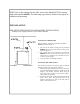
NOTE: Due to the redesign for the 2002 series of the Model 20/ZC20, starting with serial number 003908 . The following steps must be followed for proper installation and operating. INSTALLATION MOUNTING TRIM PANELS FOR MASONRY INSTALLATION (Changes refer to pages 9 and 10 in your owners manual) POSITIONING THE HEATER When positioning the heater, the following conditions MUST be met! (See Figure 2) 1. 2. 3.
3. 4. 5. FIGURE 3 MOUNTING TRIM PANELS 6. 7. 8. 9. 10. 11. 12. 13. 14. 15. Slide the unit out of the fireplace far enough to work behind the trim panel reference lines. Mount the side trim panels. (See Figure 3) a. Position the trim panel on the reference line. b. Drill mounting holes in center of trim panels mounting brackets to allow for adjustment in and out if necessary. c. Mount the trim panel using the self-tapping screws provided. Place top panel back on reference mark.
FINAL CHECK 1. 2. 3. 4. Recheck the specified clearances. Remove all foreign material from the firebox area. Open the primary air draft and damper bypass. Plug the power cord into a 115V AC outlet. Set switch to “Manual” position to ensure motor operates properly. 5. Place crumpled pieces of newspaper in the stove. Light it and close the door. Ensure that the stove draws properly through the primary drafts. 6. Check for smoke leaks around the door. 7.
SECTION III RESIDENTIAL FREESTANDING ROOM HEATER INSTALLATION INSTALLATION PRECAUTION Extensive field and laboratory testing has shown that catalytic stoves perform best as freestanding stoves when vented into a masonry chimney if: 1. 2. 3. A rain cap is installed on the chimney. Height of chimney is at least 15 feet high. Location of chimney is interior (not on an outside wall). NOTE: Certain types of double wall pipe (close clearance) also cause a substantial drop in flue gas temperature.
MINIMUM CLEARANCES The New Buck Corporation Model 20 must be installed in compliance with the instructions contained in this manual. CLEARANCE FROM COMBUSTIBLE WALLS AND CEILINGS (Using single wall chimney connector) The minimum lateral distance between any part of the room heater and combustible walls is shown in Figures 1 and 2.
Close clearance installations using listed Close Clearance pipe and 2100o HT chimney system from approved manufacturer’s list. (See page 18) 12” FIGURE 3 WALL INSTALLATION FIGURE 4 CORNER INSTALLATION TOOLS FOR INSTALLATION Drop Cloth Electric Drill with 3/32” drill bit 5/16” combination wrench 5/16” magnetic socket chuck adapter, 5/16” wrench (box or socket) or adjustable wrench Socket Set Tape Measure Pencil Level PREPARING THE STOVE FOR INSTALLATION 1. 2. 3. 4. 5. 6. 7. 8. 9.
PREPARING THE ROOM HEATER LOCATION 1. 2. 3. 4. Select an installation location that will give the best airflow from the front of the heater to the remainder of the home. Place the protective floor pad in position. Place the unit on the pad making sure the minimum clearance specifications are met. If connecting to an existing masonry flue, first ensure that the flue conforms to the NFPA-211 Code and/or consult your local code for proper procedures.
B. Wall Exit into Metal Tee-Box 1. 2. 3. 4. 5. 6. Mark the plumb line on the wall directly behind the center of the heater. (See Figure 6) Place the vertical portion of the heater pipe and the elbow in position and project a point onto the plumb line level with the center of the elbow. Measure up so there will be at least 1/4” rise per foot of horizontal connector pipe, maintaining clearances to the ceiling as noted in Figure 6. This will give you the center of the hole for the chimney penetration.
(b) Selected or fabricated in accordance with the conditions and clearances as stated in NFPA-211 code. Any unexposed metal that is used as part of a wall pass-through system and is exposed to flue gases shall be constructed of stainless steel or other equivalent material that will resist corrosion, softening, or cracking from flue gases at temperatures up to 1800o F.
FINAL CHECK 1. Recheck the specified clearances. 2. Remove all foreign material from the firebox area. 3. Open the primary air draft and damper bypass. 4. Plug the power cord into a 115V AC outlet. Set switch to “Manual” and rheostat to “High” position to ensure motor operates properly. 5. Place crumpled pieces of newspaper in the stove. Light it and close the door. Ensure that the stove draws properly through the primary draft. 6. Check for smoke leaks around the door. 7.
SECTION IV MOBILE HOME ROOM HEATER INSTALLATION WARNING: DO NOT INSTALL IN SLEEPING ROOM. CAUTION: The structural integrity of the mobile home floor, wall, and ceiling/ roof must be maintained.
Clearance from combustible walls using listed Close Clearance pipe and 2100o HT chimney system from approved manufacturer’s list. (See page 18) FIGURE 1 WALL INSTALLATION FIGURE 2 CORNER INSTALLATION FLOOR PROTECTION If the room heater is to be installed on a combustible floor, a non-combustible pad must be placed below it to protect the floor from burning material from the stove. The pad must be 36” wide by 37” deep for the Model 20. Tests were conducted without a floor protector.
PREPARING THE HEATER FOR INSTALLATION 1. 2. 3. 4. 5. 6. 7. 8. 9. Inspect the unit for any obvious physical damage. Plug the power cord into a 115V AC outlet. Set switch to “Manual” and rheostat to “High” position to ensure motor operates properly. Check the primary air draft control to ensure that it operates freely. Check the operation of the damper bypass control to ensure that it will open and close properly. Remove any items from within the firebox.
OUTSIDE AIR PEDESTAL KIT PROTECTIVE PAD #10 X 1 OUTSIDE AIR DUCT MOBILE HOME FLOOR FIGURE 3 DETERMINING THE CHIMNEY LOCATION 1. 2. Suspend a plumb bob from the ceiling above the unit so that the weight is hanging in the center of the flue exit. (A small weight on a string will serve as a plumb bob.) Mark the ceiling where the string is suspended to locate the center of the chimney hole.
RAIN CAP RAIN CAP 2FT. 2FT. STORM COLLAR STORM COLLAR FLASHING FLASHING NEW BUCK CORP. FIRESTOP RADIATION SHIELD NEW BUCK CORP. FIRESTOP RADIATION SHIELD 1. 2. 3. 4. 5. 6. 7. 20 FT. MAX. TYPICAL OUTSIDE AIR DUCT THROUGH FLOOR WHEN NOT UNDERPINNED OUTSIDE AIR DUCT TROUGH UNDERPINNING FINAL CHECK 3 FT. TYPICAL FIGURE 5 Recheck the specified clearances. Remove all foreign material from the firebox area. Open the primary air draft and damper bypass. Plug the power cord into a 115V AC outlet.
SECTION V PRE-FAB INSERT INSTALLATION INSTALLATION PRECAUTIONS This room heater is listed by Warnock-Hersey Laboratories for installation into the following Zero-Clearance Cabinet Models. These are: MAJESTIC—M-36, M-43, L-36, L-42, MD36, MD42, MD36-AO, MD42-AO HEATILATOR—FP36, 3036, 3042, 3048, 3138, 3138 EP PREWAY—DW36, DW42, BI36, BI42, BI36B, BI42B, BI36EM, BI42EM, BI36CEM, BR42CEM, BI36SEM, BI42SEM NOTE: A Preway unit has to use insert trim panels.
4. 5. 6. Thoroughly clean the fireplace of ashes and soot. Check the chimney and smoke chamber for excessive buildup of creosote or soot. Also, check for obstructions, such as birds’ nest. If the chimney is excessively dirty, clean it, or have someone clean it professionally BEFORE installing or using the room heater. The Firebrick, Ash Lip, Smoke Baffle, and Smoke Shelf may also be removed if necessary to provide room for the Model 20.
MINIMUM CLEARANCE TO COMBUSTIBLES INCREASER FIGURE 2 PACK TIGHT WITH CERAMIC WOOL (DO NOT USE GLASS WOOL). 6” FLEX PIPE OR ADJUSTABLE ELBOW FIGURE 3 C. Sealing Trim Kit 1. This third method of installation is to use the masonry fireplace trim kit to seal the stove to the Pre-Fab fireplace. CAUTION! Although this method is a tested and approved method, some codes may not allow this type installation so be sure to check local codes for approval prior to making this type of installation.
2. To complete this installation, follow the basic masonry fireplace trim kit installation instructions except: The trim kit may have to be cut down in size so as not to block any cooling vents/chambers of the PreFab Fireplace. 3. To complete methods 1 and 2: Position the heater into the Pre-Fab Fireplace and center the flue exit under the connector. 4. Slide the connector (or slip connector) down into the flue exit of the heater approximately 3/8”.
SECTION VI WOOD HEATER SAFETY Certain safety hazards are inherent in any wood heater installation. You should be aware of these so that a safe and proper installation can be made. 1. 2. FAULTY CHIMNEY: An older masonry chimney should be thoroughly checked to be sure there are no holes or weak spots which could allow sparks or hot gases to escape. HEAT CONDUCTION: Placing combustible materials too close to a heater or chimney can be a fire hazard.
SECTION VII OPERATION This section of the manual is to help you get the maximum efficiency and maximum smoke (particulate) reduction from your heater. If you should experience any difficulty or have any questions concerning your heater, contact your dealer for assistance. Build a fire for maximum efficiency. This model burns wood and extracts heat so efficiently, a large fire is not necessary. A large fire not only wastes energy, it usually results in the home being too warm for comfort.
and door to rake the wood and coals into a pile near the front center of the firebox. (Be certain wood chunks are pulled out of the rear corners.) Close door and bypass damper. This step will assure continued combustion and thorough burning of the wood. D. High-Burn Rate—Set primary air control wide open. . Set the Auto-Off-Manual switch to the Auto position. Wood Loading—During refueling, open the bypass damper, open the door, and add wood. Immediately close door and bypass damper.
OPERATING AND SAFETY HINTS: When preparing to refuel the heater, open the bypass damper (taking the heater out of catalytic mode) and wait for the smoke to clear out of the firebox before opening the door. Burn only natural wood in your catalytic heater. You should not burn trash or garbage, artificial or paper logs, gift wrapping, treated or painted wood, nor should you start a fire with lighter fluid or chemical starter.
SECTION VIII PREVENTIVE MAINTENANCE / PARTS REPLACEMENT Check Chimney A. The chimney should be cleaned as necessary to remove creosote, soot, leaves, birds’ nests, etc. (Refer to Page 27, #5 Creosote Formation.) B. A neglected chimney can eventually cause a draw restriction or can ignite and burn hot enough to cause damage to the chimney. C. For proper inspection the chimney should be cleaned. D.
a. b. Properly functioning catalysts will be exhibiting a uniform glow from one end to the other (indicating ignition). Physically degraded catalysts will have cold places (areas not igniting) where plugging, crumbling, or other degradation has occurred. If this occurs, the monitor probe temperature will not increase at a normal rate.
4. Using penetrating oil, generously lubricate the four (4) bolt threads holding the catalyst housing in place. Allow to penetrate. 5. Using a 9/16” wrench or 9/16” socket, loosen the four (4) bolts and remove the catalyst housing (drop down) and place in a suitable work area. 6. Using needle nose pliers, grasp the front edge of the stainless steel “can” which houses a catalytic element and pull upward. 7.
OPERATION OF SWITCH With Power Cord Plugged Into 115V AC Outlet. (A) For Auto position push in top of switch. When the room heater becomes warm enough the Room Air Blower will come on and stay on until your room heater falls below the activating temperature for the thermostat. (B) For Off position place the switch in the middle position. (C) For Manual position push in on the bottom of the switch. This will allow your Room Air Blower to operate without the thermostat being activated.
SECTION IX CATALYTIC TROUBLESHOOTING CONTENTS Definitions Possible Problems Plugging Extreme Temperatures Flow Restrictions Creosote Build-up Chemical Deactivation Excessive Handling Condensation in Chimney Backpuffing Non-uniform flow Troubleshooting Heater Related Problems 1. Sluggish Heater Performance 2. Drop in Overall Efficiency 3. High Fuel Consumption 4. Backpuffing 5. Smoke Rollout When Heater Door Is Opened 6. Low Catalytic Temperature 7.
DEFINITIONS AIRTIGHT HEATER—In an airtight heater, all air enters in through the inlets. Generally, non-airtight stoves are not as efficient and their level of heat output is less controllable than that of an airtight. BURN CYCLE—Time span between refuelings in which the wood is reduced to a bed of hot coals. BYPASS—Movable door inside a woodstove that is opened when the stove door is opened to give a path of least resistance to smoke to prevent roll-out. CREOSOTE—Condensed wood-gas vapor.
POSSIBLE PROBLEMS Problems encountered with the operation of catalytic-combustor equipped wood heaters are usually the same as those experienced in the operation of traditional wood heaters. Our experience has shown that adoption of good operating practices will eliminate most of these problems. In addition, it should be noted that problems with catalytic combustors are rare-fewer than 1 percent of combustors are returned for any reason.
Backpuffing-A hot combustor (above 1400o F) can sometimes act like a glow plug (spontaneous combustion ignitor). Usually the wood gas-to-air mixture is either too lean or too rich to form a highly flammable mixture. There are times when this mixture is just right within the firebox during the normal burning process. If the combustor is running at or above the ignition temperature of the mixture, spontaneous combustion will result, causing the stove to vent puffs of smoke.
3. 4. 5. 6. Problem High Fuel Consumption Backpuffing Smoke Rollout When Heater Door Is Opened Low Catalytic Temperature Possible Cause Inexperience in catalytic operation 1. 2. Improper regulation of draft or inlet air 2. 3. 3. 4. Burning wet, unseasoned wood or pitchy spongy wood Cold, windy weather 5. 6. 7. Smoke bypassing combustor Bypass stuck out Combustor not engaged 5. 6. 7. 8. Combustor not functioning 8. 1. 2. Gusts of wind Hot combustor (Above 1400o F) 1. 2. 3.
Problem 7. Creosote Running From Draft Inlet Openings 6. Possible Cause Heater dampered down too much 6. 7. Combustor not functioning 7. 1. Burning wet, pitchy woods 1. Burn dry, seasoned wood 2. Burning too much wood in one load 2. 3. Cool heater walls 3. Burn reasonably sized loads so the combustor has a chance to burn the wood gases that are produced. Keep a good bed of coals in the heater 1. 2. Leading bypass baffle plate Types and amounts of wood burned 1. 2. 3.
3. Problem Heavy Concentration of Smoke Leaving Chimney 1. 2. 3. 4. 5. Rusted or Corroded Flue Parts Odor-Both Inside and Outside The Home Poor-Drafting Chimney 1. Solution Water vapor is normal and should be of little concern 2. Burn dry, seasoned wood 3. See section on “CombustorRelated Problems: Replace warped bypass. Close bypass. 4. Bypass warped or in open position 4. 1. Added moisture from efficient burning 1. 2. Overheated flue parts due to a chimney fire 2. 3. Age.
LESS THAN 10 INCHES GREATER THAN 10 FT. 10 FT. 2 FT. 3 FT. 2 FT. 3 FT. METAL CHIMNEY 2 FT. MINIMUM HEIGHT ABOVE THE ROOF WITHIN 10 FT. HORIZONTALLY MASONRY CHIMNEY CHIMNEY “10 FT.” RULE (MINIMUM HEIGHTS) Stack wood in criss-cross pattern under a shelter to allow air flow to dry the wood and to keep wood from rain. Green wood may have 50-60% moisture content. Wood seasoned outside uncovered may have 40% moisture content.
COMBUSTOR-RELATED PROBLEMS Problem 1. Plugging Possible Cause 1. Solution Burning materials that produce a lot of char and fly ash Burning wet, pitchy wood or burning large loads of small diameter wood with the combustor in the operating position without light-off taking place 1. 3. Combustor not functioning. If proper burning procedures have been followed to no avail, the combustor is not functioning. 3. 2. 2. Do not burn materials such as garbage, gift wrap or cardboard Burn dry, seasoned wood.
6. Problem Substrate Cracking— Mechanical 1. Possible Cause Mishandling or abuse 1. 7. Substrate Crumbling 1. Extreme thermal shock 1. 2. High draft 2. 1. Variation in color from combustor to combustor or within a combustor can occur (new combustors) 1. 8. Color Variations Solution Handle with care Combustor being continually overfired. Reduce burn rate. Do not exceed .06” of water draft.
Zero Clearance Cabinet Model ZC20 For use with Fireplace Model 20 only FEATURES PREPARATION OPERATION INSTALLATION MAINTENANCE SAFETY Contact your insurance company for coverage and installation inspection SAFETY NOTICE If this cabinet and intended fireplace are not properly installed, a house fire may result. For your safety, follow the installation directions. Contact local building or fire officials about restrictions and installation inspection requirements in your area.
SECTION I RESIDENTIAL INSTALLATIONS PARTS REQUIREMENTS Listed NEW BUCK CORP. Model ZC20 Part Description/Part # Zero clearance cabinet assembly with Model 20 fireplace installed UL Listed and factory approved Chimney Systems Description Simpson Dura Vent Security Selkirk Metal Bestos Metal Fab - 6” 2100o HT Type “DP” Chimney 6” “ASHT” High Temp Chimney 6” Model SSII Type HT Chimney 6” 2100o HT Chimney CAUTION: Read through all of these instructions carefully.
F. DO NOT build a fire directly inside the ZC Cabinet. It is designed solely for housing the Model 20 Stove. G. WARNING: This fireplace has not been tested for use with a chase above the roof. H. Do not connect this unit to a chimney serving another appliance. SELECTING A CHIMNEY INSTALLATION AND LOCATION There are two basic types of chimney installations possible with the ZC20; straight up through a ceiling, and chase installation, either outside or inside.
NOTE: Chase Installation: (See Figure 3.) A chase is an enclosure built specifically to house a chimney. The interior of a chase is open from the ZC20 to the roof, eliminating the need to cut through ceilings and the roof. Normally, a chase is built outside and against the exterior wall of a home. A hole is cut through the wall, and the ZC20 is located in the bottom of the chase, with the front of the unit flush with the interior wall.
6. Obtain the listed and approved chimney installation instructions and follow exactly. a) Obtain the starter section of pipe and install on the ZC20 cabinet. It may be necessary to crimp the inside of the starter pipe to ease installation into the ZC20 cabinet. b) Obtain the two short sheet metal “ell” brackets and sheet metal screws provided with the ZC20 and secure the starter section of pipe to the ZC20 cabinet.
7. The ZC20 cabinet is now ready for framing as follows: a) Frame the ZC20 using 2”x4” studs or local building code framing. Some minor framing restrictions are required: 1. Adjacent side walls must be at least 16” from the outer edge of the ZC20 trim panel 2. The overall opening dimensions must be at least 37 15/16” wide and 34 5/8” high. NOTE: Maintain 1 1/2” clearance at the side walls of the cabinet and combustible material. b) 2”x4” framing above the unit must be turned flat.
8. Next construct the hearth extension out of non-combustible inorganic building materials as follows: a) The hearth extension must extend 17” in front of the rough framed opening on the ZC20. b) The hearth extension width must be at least 37 15/16”. c) The hearth extension must be made of brick 2” thick, a listed “Hearth Extension” or “Floor Protector”, or a hearth extension made of non-combustible inorganic material with a K* factor of: K = 2.5 BTU ((HR) (ft2) (oF/in.
TOP FRONT TRIM PANEL BRASS TRIM RIGHT SIDE TRIM PANEL BLACK WHITE HEATER POWER CORD GROUND REAR COVER PLATE RECEPTACLE BOX FIGURE 7 POWER HOOK-UP 10. Now, finish the wall around the ZC20 using brick, rock, sheetrock, paneling, or any type finishing material. CAUTION: Do not block any openings designed into the unit. 11. Install a mantel above the unit if desired. Note that a combustible mantel must be positioned at least 12” above the top of the ZC20 cabinet.
SECTION II MOBILE HOME INSTALLATIONS PARTS REQUIREMENTS Listed NEW BUCK CORP.
F. G. H. I. DO NOT build a fire directly inside the ZC20. It is designed solely for housing the Model 20. WARNING: Do not install in sleeping room. CAUTION: The structural integrity of the mobile home floor, wall, and ceiling/roof must be maintained. Do not connect this unit to a chimney serving another appliance. FRAMING CONSTRUCTION AND INSTALLATION Except as noted, the ZC20 can be installed almost anywhere you desire. There are, however, a few clearance and framing restrictions that must be followed.
5. 6. Obtain the Listed and Approved Chimney Installation instructions and follow exactly. a) Obtain the starter section of pipe and install on the ZC20 cabinet. It my be necessary to crimp the inside of the starter pipe to ease installation into the ZC20 cabinet. b) Obtain the two short sheet metal “ell” brackets and sheet metal screws provided with the ZC20 and secure the starter section of pipe to the ZC20 cabinet.
Optional Fire Code Sheet Rock And Metal Fire Stop TOPPER STORM COLLAR ROOF FLASHING 2 In. Min. CAUTION: Refer to chimney manufactures instructions for assembly and disassembly of chimney parts. Be sure to follow chimney instructions for proper clearances to combustibles and proper air spacing required. TRIPLE WALL PIPE 2 “X 4” STUDDING USE FIRE CODE SHEET ROCK 15FT. MAX.
K Factors of Alternate Materials: Material Ceroform 126 Limestone Concrete Sandstone Marble K .21 8.0 8.0 13.0 18.0 Required Thickness 1/8” 3.2” 3.2” 5.2” 7.2” Hearth extension or floor protector thickness above four (4) inches is generally not acceptable due to cost, floor load capacity, and look. The alternate we recommend is using Ceroform No. 126 millboard 1/8” thick minimum and putting any type decorative brick or stone (any thickness) on top of it.
CLEANING THE UNIT A. The unit should be lightly sanded with fine sandpaper or steel wool, then repainted or touched up with high temperature black paint. B. If the unit is located in a moist or damp location, check thoroughly for signs of condensation during times when the unit is not in use. C. When the heating season is over, the unit can be cleaned out completely with a wire brush or cloth to help eliminate ash and burned wood smell. SAFETY PRECAUTIONS 1.
PREVENTIVE MAINTENANCE/ SAFETY PRECAUTIONS CHIMNEY A. The chimney should be cleaned as necessary to remove creosote, soot, leaves, birds’ nests, etc. CREOSOTE-FORMATION AND NEED FOR REMOVAL When wood is burned slowly, it produces tar and other organic vapors, which combine with expelled moisture to form creosote. The creosote vapors condense in the relatively cool chimney flue of a slow-burning fire. As a result, creosote residue accumulates on the flue lining.
NEW BUCK CORPORATION (NBC) “LIMITED WARRANTY” FOR NBC RELATED PRODUCTS PLEASE READ THIS WARRANTY CAREFULLY PRODUCTS COVERED This warranty covers the new heating unit so long as it is owned by the original purchaser, including optional and standard accessories purchased at the same time, subject to terms, limitations, and conditions herein set out.