MODEL 261 NON-CATALYTIC UNIT BUCK STOVE OR TOP EXIT REAR EXIT FEATURES PREPARATIONS INSTALLATION OPERATION MAINTENANCE SAFETY SAFETY NOTICE IF THIS HEATER IS NOT PROPERLY INSTALLED, A HOUSE FIRE MAY RESULT. FOR YOUR SAFETY, FOLLOW THE INSTALLATION INSTRUCTIONS. CONTACT THE AUTHORITY HAVE JURISDICTION ( SUCH AS MUNICIPAL BUILDING DEPARTMENT, FIRE DEPARTMENT, FIRE PREVENTION BUREAU, ect.) SHOULD BE CONSULTED BEFORE INSTALLATION TO DETERMINE THE NEED TO OBTAIN A PERMIT.
TABLE OF CONTENTS Important Instructions ……………………………………………………………………...…...2 SECTION I: Introduction………………………………………………………………………..3 Cautions………………………………………………………………………………………….5 SECTION II: Residential Freestanding Vertical Installation ………………..…………...…...6 Minimum Clearances / Floor Protection and Combustibles……………………………………. 6 Preparing Stove For Installation ………………………………………………………………..7 How to locate chimney exit, and install………………….…………………………………..…..8 A.
INSTALLATION, OPERATION, AND MAINTENANCE INSTRUCTIONS MODELS 261 READ THIS FIRST IMPORTANT INSTRUCTIONS WARNING THESE UNITS GENERATE A LOT OF HEAT, SO TREAT THEM WITH CARE. HOT WHILE IN OPERATION! KEEP CHILDREN, CLOTHING AND FURNITURE AWAY. CONTACT MAY CAUSE SKIN BURNS. READ ALL INSTRUCTIONS BEFORE INSTALLING AND USING THE APPLIANCE. FAILURE TO FOLLOW INSTRUC TIONS MAY RESULT IN PROPERTY DAMAGE, BODILY INJURY, OR EVEN DEATH. SAVE THESE INSTRUCTIONS FOR FUTURE REFERENCES. • The New Buck Corp.
CAUTION YOUR CHIMNEY OR FLUE MUST BE CORRECTLY SIZED. A CHIMNEY OR FLUE THAT IS TOO SMALL OR LARGE IN DIAMETER, OR TOO SHORT, CAN CAUSE YOUR STOVE TO SPILL SMOKE WHEN THE DOOR IS OPENED. SECTION I INTRODUCTION Your new MODEL 261 is a non-catalytic unit designed to meet the most stringent emissions standards without the use of a catalytic combustor. This effect is achieved through the use of secondary air which is mixed with primary air in the unit’s firebox.
POSSIBLE TOOLS NEEDED FOR INSTALLATION If you decide to install your own stove, there are several hand tools you may need to do the job. If you do not already have them, they are readily available at most hardware stores.
CAUTION THE UNIT IS PAINTED WITH A SPECIALLY FORMULATED HIGH TEMPERATURE PAINT THAT CURES DURING THE FIRST TWO OR THREE FIRINGS. YOU MAY NOTICE A SLIGHT SMOKING EFFECT AND AN ODOR OF BURNING PAINT WHEN YOU BUILD THE FIRST FIRES. THIS IS NORMAL AND IS NOT A CAUSE FOR ALARM. IN SOME CASES, THESE FUMES WILL ACTIVATE A SMOKE ALARM. OPENING A WINDOW NEAR THE UNIT WILL ALLOW THESE FUMES TO ESCAPE. DO NOT BUILD A LARGE, ROARING FIRE UNTIL THIS CURING IS COMPLETE OR THE HEATER FINISH MAY BE DAMAGED.
SECTION II RESIDENTIAL FREESTANDING VERTICAL EXIT INSTALLATION For optional vertical exit installation locations refer back to table of contents Section II MINIMUM CLEARANCES TO FLOOR AND COMBUSTIBLES See minimum floor protector measurements ,and also for minimum clearances to combustibles, See Pages, and Figures below A. Vertical Exit Single Wall Pipe( Page9, Figure3 ) B. Vertical Exit DVL ( Page11, Figure5 ) C. Vertical Wall Exit ,Single Wall Pipe, Elbow,103 HT Chimney and T-BOX(Page13, Figure7) D.
Select an installation location that will give the best airflow from the front of the heater to the remainder of the home. PREPARING THE STOVE FOR INSTALLATION 1. Inspect the unit for any obvious physical damage. 2. Plug the power cord into a 115V AC outlet to test the motor and fan when optional motor is being used. “Do not run power cord under unit or in high traffic areas”. 3. Check the primary air draft control to ensure that it slides freely. 4. Remove any items from within the firebox.
PREPARING THE ROOM HEATER LOCATION 1. Select an installation location that will give the best airflow from the front of the heater to the remainder of the home. 2. Place the protective floor pad in position. 3. Place the unit on the pad making sure the minimum clearance specifications are met. 4. If connecting to an existing masonry flue, first ensure that the flue conforms to the NFPA211 Code and/or consult your local code for proper procedures.
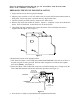
A. Vertical exit using (6" Single Wall pipe minimum 24 ga. blued or black pipe and any listed 2100° UL 103 HT. TYPE Chimney). With standard close clearance shield and pipe shield. Model 261 minimum clearance to combustibles. Figure 3. Figure 4. BACK BACKWALL WALL F GD F LISTED 2100° UL 103 HT TYP.
HOW TO LOCATE CHIMNEY EXIT, AND INSTALL B. Vertical Exit using (6" DVL Close Clearance pipe, or Shielded Single wall pipe, and any Listed 2100° UL 103 HT chimney). With standard close clearance shield and pipe shield. NOTE: For minimum clearances (See Page 11, Figure 5). 1. Suspend a plumb bob from the ceiling above the unit so that the weight is hanging in the center of the flue exit. (A small weight on a string will serve as a plumb bob.
B. Vertical exit using (6" DVL Close Clearance pipe or Shielded Single wall pipe, and any listed 2100° UL 103 HT. TYPE Chimney). With standard close clearance shield and pipe shield. Model 261 minimum clearance to combustibles. Figure 5. Figure 6. CONTEMPORARY CAP BACK WALL BACK WALL F GD F LISTED 2100° UL 103 HT TYP.
HOW TO LOCATE CHIMNEY EXIT, AND INSTALL C. Vertical Wall Exit using (6" Single Wall pipe minimum 24 ga. blued or black with elbow, and any Listed 2100° UL HT chimney and Listed 2100° UL HT T-Box assembly). With standard close clearance shield and pipe shield NOTE: For minimum clearances (See Page 13, Figure 7). 1. Mark the plumb line on the wall directly behind the center of the heater. (See Page 13, Figure 8). NOTE: When using 24# ga.
C. Vertical wall exit using (6" Single Wall Pipe minimum 24 ga. blued or black pipe and elbow pipe, and any listed 2100° UL 103 HT. TYPE Chimney and Listed 2100° UL HT T-Box assembly). With standard close clearance shield and pipe shield. Model 261 minimum clearance to combustibles. BACK WALL WALL BACK E H GD F E A A C C C PROTECTOR SIDE WALL BB Figure 7.
HOW TO LOCATE CHIMNEY EXIT, AND INSTALL D. Vertical Wall Exit using (6" DVL Close Clearance Pipe and Elbow, and any Listed 2100° UL HT chimney and Listed 2100° UL HT T-Box assembly). With standard close clearance shield and pipe shield NOTE: For minimum clearances (See Page 15, Figure 9). 1. Mark the plumb line on the wall directly behind the center of the heater. (See Page 15, Figure 10.) NOTE: When using DVL Close Clearance Pipe , “maintain manufacturers minimum clearances" between pipe and ceiling. 2.
D. Vertical wall exit using (6" DVL Close Clearance pipe with elbow) , and any listed 2100° UL 103 HT. TYPE Chimney). With standard close clearance shield and pipe shield. Model 261 minimum clearance to combustibles. Figure 9. BACK WALL BACK WALL E H F F D G PROTECTOR SIDE WALL BB C C C C DG E A A A B C D E F G MODEL 261 14” 4" 14" 7" 8" 3" 16" H NOTE: All clearances are to combustibles with all low clearance shields and double wall pipe with elbow, and minimum floor protector.
HOW TO LOCATE CHIMNEY EXIT, AND INSTALL E. Vertical exit into masonry flue using (6" Single Wall pipe minimum 24 ga. blued or black pipe with Elbow). With standard close clearance shield and pipe shield. NOTE: For minimum clearances (See Page 17, Figure 11). 1. Before connecting these units to a masonry chimney, determine that the masonry flue pass-through connector thimble meets the NFPA-211 Code, and local building codes, and is a minimum of 18" from the ceiling.
E. Vertical exit into masonry flue using (6" Single Wall pipe minimum 24 ga blued or black pipe with elbow) With standard close clearance shield and pipe shield. Model 261 minimum clearance to combustibles. Figure 11. BACK WALL BACK WALL E H F F D G PROTECTOR SIDE WALL BB C C C C DG E A A A B C D E MODEL 261 13” 8" 13" 12" 8" F G 3" 16" H 10" NOTE: All clearances are to combustibles with all low clearance shields and single wall pipe with elbow, and minimum floor protector.
HOW TO LOCATE CHIMNEY EXIT, AND INSTALL F. Vertical exit into masonry flue using (6" DVL Close Clearance pipe with Elbow). With standard close clearance shield and pipe shield. NOTE: For minimum clearances (See Page 19, Figure 13). 1. Before connecting these units to a masonry chimney, determine that the masonry flue passthrough connector thimble meets the NFPA-211 Code, and local building codes “maintain manufacturers minimum clearances” from the ceiling.
F. Vertical exit using (6" DVL Close Clearance pipe with Elbow) into masonry flue. With standard close clearance shield and pipe shield. Model 261 minimum clearance to combustibles. Figure 13. BACK WALL BACK WALL E E A A PROTECTOR SIDE WALL F BB HGD F C C C C DG A B C D E F G H MODEL 261 14” 4" 14" 7" 8" 3" 16" 10" NOTE: All clearances are to combustibles with all low clearance shields and single wall pipe with elbow, and minimum floor protector.
SECTION III RESIDENTIAL FREESTANDING REAR EXIT INSTALLATION For optional rear exit installation locations refer back to table of contents Section III MINIMUM CLEARANCES TO FLOOR AND COMBUSTIBLES See minimum floor protector measurements ,and also for minimum clearances to combustibles, (Pages, and Figures below) A. Rear Exit Into Masonry Flue Using Single Wall Pipe( Page23, Figure17 ) B. B. Rear Exit Into Masonry Flue Using DVL Close Clearance Pipe( Page25, Figure19 ) C.
Select an installation location that will give the best airflow from the front of the heater to the remainder of the home. PREPARING THE STOVE FOR INSTALLATION 1. Inspect the unit for any obvious physical damage. 2. Plug the power cord into a 115V AC outlet to test the motor and fan when optional motor is being used. “Do not run power cord under unit or in high traffic areas”. 3. Check the primary air draft control to ensure that it slides freely. 4. Remove any items from within the firebox.
PREPARING THE ROOM HEATER LOCATION 1. Select an installation location that will give the best airflow from the front of the heater to the remainder of the home. 2. Place the protective floor pad in position. 3. Place the unit on the pad making sure the minimum clearance specifications are met. 4. If connecting to an existing masonry flue, first ensure that the flue conforms to the NFPA-211 Code and/or consult your local code for proper procedures.
A. Rear exit into Masonry Flue using (6" Single Wall pipe minimum 24 ga blued or black pipe). With standard close clearance shield and pipe shield. Model 261 minimum clearance to combustibles. BACK WALL BACK WALL E E G F G F PROTECTOR SIDE WALL BB Figure 17. C C C C DD A A A B C D E F G MODEL 261 13” 13" 13" 16" 8" 3" 10" NOTE: All clearances are to combustibles with all low clearance shields and single wall pipe , and minimum floor protector.
HOW TO LOCATE CHIMNEY EXIT, AND INSTALL B. Rear exit into Masonry Flue (6" Using DVL Close Clearance Pipe). With standard close clearance shield and pipe shield. NOTE: For minimum clearances (See Page 25, Figure 19). 1. Before connecting these units to a masonry chimney, determine that the masonry flue pass-through connector thimble meets the NFPA-211 Code and local building codes and is a minimum of 18" from the ceiling.
B. Rear exit into Masonry Flue using (6" DVL Close Clearance pipe). With standard close clearance shield and pipe shield. Model 261 minimum clearance to combustibles. Figure 19. BACK WALL BACK WALL E E F F PROTECTOR SIDE WALL BB GG C C C C DD A A A B C D E MODEL 261 13” 13" 13" 16" 8" F G 3" 10" NOTE: All clearances are to combustibles with all low clearance shields and Double wall pipe , and minimum floor protector.
HOW TO LOCATE CHIMNEY EXIT, AND INSTALL C. Rear Exit to Vertical then to Horizontal into Masonry Flue using (6" DVL Close Clearance pipe and Elbow’s). With standard close clearance shield and pipe shield. NOTE: For minimum clearances (See Page 27, Figure 21). Before connecting these units to a masonry chimney, determine that the masonry flue passthrough connector thimble meets the NFPA-211 Code,and local building codes, “maintain manufacturers minimum clearances”from the ceiling.
C. Rear exit Vertical then to Horizontal into Masonry Flue using (6" DVL Close Clearance pipe ,and Elbows) . With standard close clearance shield and pipe shield. Model 261 minimum clearance to combustibles Figure 21. BACK WALL WALL BACK E F F PROTECTOR SIDE WALL BB GG E C C C C DD A A A B C D E MODEL 261 13” 13" 13" 16" 8" F G 3" 10" NOTE: All clearances are to combustibles with all low clearance shields, and double wall pipe with elbows ,and minimum floor protector.
Rear exit into Masonry Fireplace using (6" Single Wall pipe, minimum 24 ga. blued or black pipe) . With standard close clearance shield and pipe shield NOTE: For minimum clearances (See Figure 23). INSTALLATION PREPARATION D. 1. Locate furniture and other materials away from the front of the fireplace to allow free access to the fireplace. 2. Thoroughly clean the fireplace or flue of ashes and soot. 3. Check the chimney and smoke chamber for excessive buildup of creosote or soot.
D. Rear exit in to Masonry Fireplace using (6" single wall pipe, minimum 24 ga. blued or black) . With standard close clearance shield and pipe shield NOTE: For minimum clearances (Page 29 Figure 23. also Figure 24). NOTE: Optional 2” legs Part # FA FS261 Are available when installing Model 261 into a masonry fireplace with existing height of only 24”. WITH 2" LEGS, THE TOP OF THE REAR EXIT ON THE STOVE IS BELOW 24" FROM FLOOR OR HEARTH ENABLING TO INSERT PIPE INTO MOST MASONRY FIREPLACE Figure 24.
SECTION IV Alcove Installation Vertical or Horizontal Exit For optional Vertical exit or Horizontal exit installation locations refer back to table of contents Section IV MINIMUM CLEARANCES TO FLOOR AND COMBUSTIBLES See minimum floor protector measurements, and also for minimum clearances to combustibles A. vertical exit (Page 33, Figure 27 or Page 35, Figure 29) or B. rear exit (Page 37, Figure 31). Floor Protection: When installing freestanding heater ,a floor protector must be use.
Select an installation location that will give the best airflow from the front of the heater to the remainder of the home. PREPARING THE STOVE FOR INSTALLATION 1. Inspect the unit for any obvious physical damage. 2. Plug the power cord into a 115V AC outlet to test the motor and fan when optional motor is being used. “Do not run power cord under unit or in high traffic areas”. 3. Check the primary air draft control to ensure that it slides freely. 4. Remove any items from within the firebox.
A-1. Vertical Exit Installation HOW TO LOCATE CHIMNEY EXIT, AND INSTALL A-1. Vertical Exit using (6" DVL Close Clearance pipe, or Shielded Single wall pipe, and any Listed 2100° UL 103 HT chimney). With standard close clearance shield and pipe shield. NOTE: For minimum clearances (See Page 33, Figure 27). 1. Suspend a plumb bob from the ceiling above the unit so that the weight is hanging in the center of the flue exit. (A small weight on a string will serve as a plumb bob.
ALCOVE INSTALLATION AND CLEARANCES A-1. Alcove Vertical exit using (6" DVL Close Clearance pipe, and any listed 2100° UL 103 HT. TYPE Chimney). With standard close clearance shield and pipe shield. Model 261 minimum clearance to combustibles.
A-2. Vertical Exit Installation HOW TO LOCATE CHIMNEY EXIT, AND INSTALL A-2. Vertical Wall Exit using (6" DVL Close Clearance Pipe and Elbow and any Listed 2100° UL HT chimney, and Listed 2100° UL HT T-Box assembly). With standard close clearance shield and pipe shield NOTE: For minimum clearances (See Page 35, Figure 29). 1. Mark the plumb line on the wall directly behind the center of the heater. (See Page 35, Figure 30.
ALCOVE INSTALLATION AND CLEARANCES A-2. Alcove Vertical Wall exit using (6" DVL Close Clearance pipe, Elbow and any listed 2100° UL 103 HT. TYPE Chimney). With standard close clearance shield and pipe shield. Model 261 minimum clearance to combustibles.
B-1. Rear Exit Installation HOW TO LOCATE CHIMNEY EXIT, AND INSTALL B-1. Vertical Rear Exit using (6" DVL Close Clearance Pipe and any Listed 2100° UL HT chimney, and Listed 2100° UL HT T-Box assembly). With standard close clearance shield and pipe shield NOTE: For minimum clearances (See Page 37, Figure 31). 1. Measure up so there will be at least 1/4" rise per foot of horizontal connector pipe, maintaining clearances as noted in (Page 37,Figure 31).
ALCOVE INSTALLATION AND CLEARANCES B-1. Alcove Rear exit using (6" DVL Close Clearance pipe, and any listed 2100° UL 103 HT TYPE Chimney). With standard close clearance shield and pipe shield. Model 261 minimum clearance to combustibles.
FINAL CHECK 1. Recheck the specified clearances. 2. Remove all foreign material from the firebox area. 3. Open the primary air draft. 4. Plug the power cord into a 115V AC outlet when using with optional motor. 5. Place crumpled pieces of newspaper in the stove. Light it and close the doors. Ensure that the stove draws properly through the primary draft. 6. Check for smoke leaks around the door. CAUTION Open the doors and check for smoke escaping from the front of the stove.
SECTION V FREESTANDING MOBILE HOME INSTALLATION MINIMUM CLEARANCES TO FLOOR AND COMBUSTIBLES See minimum floor protector measurements, and also for minimum clearances to combustibles (See Page 42, Figure 35). Floor Protection: When installing freestanding heater, a floor protector must be use. Floor protection must be 3/8” minimum thickness non-combustible material or equivalent. How to use alternate materials and how to calculate equivalent thickness.
Select an installation location that will give the best airflow from the front of the heater to the remainder of the home. PREPARING THE STOVE FOR INSTALLATION 1. Inspect the unit for any obvious physical damage. 2. Plug the power cord into a 115V AC outlet to test the motor and fan when optional motor is being used. “Do not run power cord under unit or in high traffic areas”. 3. Check the primary air draft control to ensure that it slides freely. 4. Remove any items from within the firebox.
FREESTANDING MOBILE HOME INSTALLATION PREPARING THE ROOM HEATER LOCATION 1. Select an installation location that will give the best airflow from the front of the heater to the remainder of the home. (See Page 42 Figure 35 minimum clearances to combustibles). CAUTION THE STRUCTURAL INTEGRITY OF THE MOBILE HOME FLOOR MUST BE MAINTAINED. (MOVE OPENING AND/OR REPOSITION HEATER LOCATION IF NECESSARY). When installing model 261 into mobile home, heater must be secure to the structure of mobile home.
9. Now, reposition the heater on the pad being sure to line the feet up with the reference marks. 10. Slide the outside air duct up to the bottom of the heater and attach it with the screws supplied with the kit, using a wrench or ratchet. (See Page 43 Figure 38) . Note: If the mobile home is underpinned you must provide extra pipe (NOT INCLUDED IN PACKAGE) too extend out side air ducting through underpinning or foundation of mobile home.
Optional air inlet plate opening on outer bottom of unit. Pry ,and twist out inner tab till it breaks loose. Outer Bottom Of Unit Figure 36 Take measurements from bottom of heater, and use them to locate the opening for the out side air duct, place them onto protective pad. 4-1/4” OUT SIDE AIR DUCT HOLE PROTECTIVE PAD MEASUREMENT Figure 37 MEASUREMENT RAIN CAP RAIN CAP RAIN CAP Figure 38 RAIN CAP 24" min. 24" 24" min. (610 mm) min.(610mm) (610 mm) 24" min.(610mm) 36" TYP. 36" TYP. 36" TYP.
2. After locating the center of the hole install the ceiling support box, chimney, flashing and rain cap using listed chimney only. Only use pipe listed in this manual. CAUTION REFER TO CHIMNEY MANUFACTURER’S INSTRUCTIONS FOR ASSEMBLY AND DISASSEMBLY OF CHIMNEY PARTS. BE SURE TO FOLLOW CHIMNEY INSTRUCTIONS FOR PROPER CLEARANCES TO COMBUSTIBLE AND PROPER AIR SPACING REQUIRED. 3.
FINAL CHECK 1. Recheck the specified clearances. 2. Remove all foreign material from the firebox area. 3. Open the primary air draft. 4. Plug the power cord into a 115V AC outlet when using with optional motor. 5. Place crumpled pieces of newspaper in the stove. Light it and close the doors. Ensure that the stove draws properly through the primary draft. 6. Check for smoke leaks around the doors. 7. Open the doors and check for smoke escaping from the front of the stove.
SECTION VI WOOD HEATER SAFETY Certain safety hazards are inherent in any wood heater installation. You should be aware of these so that a safe and proper installation can be made. 1. FAULTY CHIMNEY: An older masonry chimney should be thoroughly checked to be sure there are no holes or weak spots which could allow sparks or hot gases to escape. 2. HEAT CONDUCTION: Placing combustible materials too close to a heater or chimney can be a fire hazard.
SECTION VII OPERATION This section of the manual is to help you get the maximum efficiency and maximum smoke (particulate) reduction from your heater. If you should experience any difficulty or have any questions concerning your heater, contact your dealer for assistance. The manufacturer recommends that for maximum performance burn seasoned hard wood. Build a fire for maximum efficiency. These models burn wood and extract heat so efficiently, a large fire is not necessary.
SECTION VIII TROUBLESHOOTING PROBLEM 1. Sluggish Heater POSSIBLE CAUSE 1. Obstruction in Chimney 2. Improperly sealed trim kit or direct connect kit 3. Manual damper in chimney is closed 4. Wet or unseasoned wood being burned 5. Poor chimney draft 48 SOLUTION 1. Check for and remove obstruction 2. (a) Check trim kit gasketing seal to fireplace and gasket as necessary to seal unit. Gasket under front bottom of stove if needed. (b) Check seal if using direct connect and correct. 3.
PROBLEM 2. High fuel consumption 3. Backpuffing POSSIBLE CAUSE SOLUTION 1. Improper regulation of draft or inlet air 1. (a) Close inlet air control as much as possible to maintain desired heat output. (b) Check gaskets, reinstall fiberglass gasketing round doors and glass as necessary 2. Improper door fitting 2. Check door gasket, check adjustment of door latch 1. Gusts of Wind 1. (a) Smoke shelf in chimney is filled with creosote & ash (b) Chimney may need wind diverter.
NEW BUCK CORPORATION (NBC) "LIMITED WARRANTY" FOR THE BUCK STOVE PLEASE READ THIS WARRANTY CAREFULLY PRODUCTS COVERED This warranty covers the New Buck Stove heating unit, so long as it is owned by the original purchaser, including optional and standard accessories purchased at the same time, subject to terms, limitations, and conditions herein set out. PRODUCTS NOT COVERED This warranty does not cover the following: Glass; Refractory material such as refractory cement or firebrick; Gaskets.
If for any reason you are dissatisfied with the suggested procedures, you may contact us in writing at: New Buck Corporation Customer Service Department P. O. Box 69 Spruce Pine, NC 28777 CONDITIONS AND EXCLUSIONS A. Replacement of parts may be in the form of new or fully reconditioned parts, at NBC's option. B There is no other express warranty. All implied warranties of Merchantability and Fitness for Use are limited to the duration of the Express Warranty. C.