MODEL 34 MAY BE INSTALLED IN A SOLID FUEL BURNING FIREPLACE, AS A ZERO CLEARANCE FIREPLACE OR WITH AN OPTIONAL SURROUND. WARNING: If the information in this manual is not followed exactly, a fire or explosion may result causing property damage, personal injury or loss of life. − Do not store or use gasoline or other flammable vapors and liquids in the vicinity of this or any other appliance. WHAT TO DO IF YOU SMELL GAS • • • • − Do not try to light any appliance.
TABLE OF CONTENTS MODEL 34 SECTION I: Safety Information........................................................................................ 3 SECTION II: Fireplace Preparation/Solid Fuel Burning Fireplace (FP)........................... 6 Fireplace Clearances(FP) .................................................................................................... 7 Gas Connection...................................................................................................................
SECTION I SAFETY INFORMATION WARNINGS IMPORTANT: READ THIS OWNER’S MANUAL CAREFULLY AND COMPLETELY BEFORE TRYING TO ASSEMBLE, OPERATE, OR SERVICE THE APPLIANCE. IMPROPER USE OF THESE LOGS CAN CAUSE SERIOUS INJURY OR DEATH FROM BURNS, FIRE, EXPLOSION, AND CARBON MONOXIDE POISONING. Early signs of carbon monoxide poisoning resemble the flu, with headaches, dizziness, and/or nausea. If you have these signs, the heater may not be working properly. Get fresh air at once! Have heater serviced.
5. If this heater is used with propane gas, do not place propane supply tank (s) inside any structure. 6. What To Do IF You Smell Gas: Shut off gas supply. - Do not try to light any appliance. - Do not touch any electrical switch; do not use any phone in your building. - Immediately call your gas supplier from a neighbor’s phone. Follow the gas supplier’s instructions. - If you cannot reach your gas supplier, call the fire department. 7.
21. All heater screens must be kept closed when operating the gas logs. 22. ”WARNING: Failure to keep the primary air opening (s) of the burner (s) clean may result in sooting and property damage.” 23. Do not use this heater for burning trash or cooking. Never place matches, paper, garbage, or any other material on top of logs or into the flames. 24. Do not install or operate this heater in areas where impurities in the air exist (such as tobacco smoke or heavy cooking grease).
SECTION II FIREPLACE PREPARATION The fireplace needs to be prepared before installing the heater. A. Turn off the gas supply to the fireplace. WARNING: BEFORE INSTALLING IN A SOLID-FUEL BURNING FIREPLACE, THE CHIMNEY FLUE AND FIREBOX MUST BE CLEANED OF SOOT, CREOSOTE, ASHES, AND LOOSE PAINT BY A QUALIFIED CHIMNEY CLEANER. “WARNING: DO NOT ALLOW FANS TO BLOW DIRECTLY INTO THE FIREPLACE. AVOID DRAFTS THAT ALTER BURNER FLAME PATTERNS.
INSTALLATION AND CLEARANCES To ensure a safe installation into a masonry or factory built fireplace, the following instructions must be carefully followed: (1) Sidewall Clearances: Clearance from the side of the fireplace opening to any adjacent combustible wall should not be less than: right side 7", left side 7". (2) Ceiling Clearances: The ceiling height should not be less than 24" from the top of the fireplace opening.
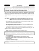
CR3329 CERAMIC LOG SET PLACEMENT, FOR MODEL 34 (3) (4) (2) (1-R) (1-L) WARNING: Failure to position the parts in accordance with these diagrams or failure to use only parts specifically approved with this heater may result in property damage or personal injury. WARNING: POSITIONING OF LOGS IS VERY CRITICAL (SEE DIAGRAM ABOVE). (1) Front Log(s) #1-R and 1-L (Slim Log(s) wrapped in cardboard box) . Place the 1-R between the front portion of the burner and log grates on the right hand side of the log base.
EMBER STOVE LOG SET PLACEMENT FOR MODEL 34 3 4 1 2 6 5 7 “MILLIVOLT ONLY” WARNING: Failure to position the parts in accordance with these diagrams or failure to use only parts specifically approved with this heater may result in property damage or personal injury. WARNING: POSITIONING OF LOGS IS VERY CRITICAL (SEE DIAGRAM ABOVE). MODEL E.S.B: 1)Rear Log, 2)Middle Log, 3)Left Top Middle Log, 4)Right Top Middle Log 5)Left Front Log 6)Right Front Log 7)Glowing Embers in front of 5 & 6 logs.
GAS PRESSURE CHECK Check the inlet pressure to the burner to ensure that it is as shown in the table below. NOTE: The pressure check point located on the right side of the valve facing burner, for SIT GASis PRESSURE CHECK Millivolt, and the left side for SIT Modulating. The appliance and its appliance main gas valve must be disconnected from the gas supply Check the inlet pressure to the burner to ensure that it is as shown in the table below.
LIGHTING INSTRUCTIONS MILLIVOLT VALVE (ITT) FOR YOUR SAFETY, READ BEFORE LIGHTING WARNING IF YOU DO NOT FOLLOW THESE INSTRUCTIONS EXACTLY, A FIRE OR EXPLOSION MAY RESULT CAUSING PROPERTY DAMAGE, PERSONAL INJURY, OR LOSS OF LIFE. A. This appliance has a pilot which must be lighted by hand. When lighting the pilot, follow these instructions exactly. B. BEFORE LIGHTING smell around the appliance for gas. Be sure to smell next to the floor because gas is heavier than air and will settle on the floor.
LIGHTING INSTRUCTIONS 1. STOP! Read the safety information on previous page. 2. Make sure the manual shutoff valve is fully closed.If equipped with thermostat set to the lowest setting. 3. Turn off all electrical power to the appliance. 4. Open access panel door located at bottom front of the appliance. 5. Turn control knob clockwise to the full “OFF” position.
• If the pilot will not stay lit after several tries, turn the gas control knob to “OFF” and call your service technician or gas supplier. IGNITOR ELECTRODE PILOT BURNER THERMO-COUPLE THERMO-PILE 12. Turn control knob counterclockwise to the “ON” position. Push the “ON/OFF” toggle switch to the “ON” position. The main burner should light. 13. Close access panel door. 14. Turn on all electrical power to the appliance. NOTE: This unit may be used with an optional Wall Thermostat.
THERMOSTAT CONTROL OPERATION • This valve operates off of millivolts produced by the generator. You may choose to use an optional Wall Thermostat or Remote control. If so, see page 22 for wiring diagram. MANUAL LIGHTING PROCEDURE 1. If the pilot cannot be lit with the piezo, it can be manually lit with the use of a paper match and a lighter rod. 2. Open access panel door located at bottom front of the appliance. 3. Place the match in the holder and light.
LIGHTING INSTRUCTION MODULATING VALVE (SIT) MANUAL VALVE (SIT) FOR YOUR SAFETY READ BEFORE LIGHTING WARNING IF YOU DO NOT FOLLOW THESE INSTRUCTIONS EXACTLY, A FIRE OR EXPLOSION MAY RESULT CAUSING PROPERTY DAMAGE, PERSONAL INJURY OR LOSS OF LIFE.” A. This appliance has a pilot which must be lighted by hand. When lighting the pilot, follow these instructions exactly. B. BEFORE LIGHTING smell all around the appliance area for gas.
LIGHTING INSTRUCTION 1. STOP! Read the safety information on preceding page 15. 2. Make sure manual shutoff valve is fully closed. 3. Turn off all electrical power to the appliance. 4. Open access panel door located at bottom front of the appliance. 5. Turn control knob clockwise to the full “OFF” position. 6. Wait five (5) minutes to clear out any gas. Then smell for gas, including near the floor. If you smell gas, STOP! Follow “B” on preceding page in the Safety Information.
11. Turn gas control knob counterclockwise to “ON” position. Continue to turn the gas control knob counterclockwise to your desired setting. 12. Close access panel door. 13. Turn on all electrical power to the appliance. CAUTION DO NOT TRY TO ADJUST HEATING LEVELS BY USING THE MANUAL SHUTOFF VALVE. TO TURN OFF GAS TO APPLIANCE SHUTTING OFF UNIT 1. Open access cover door. 2. Turn gas control knob clockwise to the full “OFF” position. 3.
THERMOSTAT CONTROL OPERATION 1. The thermostat control on this heater differs from standard thermostats. Standard thermostats simply turn the burner on and off. The thermostat used on this heater senses the room temperature and adjusts the amount of gas flow to the burner. This will increase or decrease the flame height. At times, the room may exceed the set temperature, which will cause the burner to shut off. When room temperature drops below the thermostat setting, the burner will cycle itself on again.
OPERATING INSTRUCTIONS Before operating this appliance, proceed through the following checklist. 1. Read and understand these instructions before operating this appliance. 2. Check that there are no gas leaks. If you smell gas do not attempt to light this appliance. 3. Verify that log placement is correct.
LIGHTING INSTRUCTIONS 1. STOP! Read the safety information on the reverse side of this label (page 19). 2. Make sure manual shutoff valve is fully closed. If equipped with thermostat, set to the lowest setting. 3. Turn off all electrical power to the appliance. 4. Open access door located at bottom of front of the appliance. 5. Push in gas control knobslightly and turn clockwise to the full “OFF” position.
* If the pilot will not stay lit after several tries, turn the gas control knob to “OFF” and call your service technician or gas supplier. 11. Turn control knob counterclockwise to “ON”. 12. If using unit without wall thermostat place Auto/Off/Manual switch into the manual position. If using wall thermostat place Auto Off Manual Switch into the auto position and place thermostat to a setting higher than the room temperature. 13. Close access cover door. 14. “Turn on all electrical power to the appliance.
MANUAL LIGHTING PROCEDURE 1. If the pilot cannot be lit with the piezo, it can be manually lit with the use of a paper match and a lighter rod. 2. Open access panel door located at bottom front of the appliance. 3. Place the match in the holder and light. With the left hand, turn the control knob counterclockwise to “PILOT”position. Press in gas control knob for fifteen (15) seconds. 4. Use rod to light match and ignite pilot.
FLAME CHECK A periodic check of the flames should be made. The pilot flame should always be present when the gas logs are in operation. See Figure 4. Rear Flames: The flames at the rear or at either side of the top log should be very similar, yellow in color, and should be about 3" to 4" above the large rear log for natural gas logs and about 6" for propane (LP) gas log sets. Front Flame: The flame should be 1-1/2" to 2" high and touch the back of front log. This will produce a red glow on this log.
WIRING DIAGRAM MOTOR THERMOSTAT JUMPER JUMPER JUMPER GREEN WHITE BLACK RHEOSTAT BLACK POWER CORD Figure 5 WARNING: CHILDREN AND ADULTS SHOULD BE ALERTED TO THE HAZARDS OF HIGH SURFACE TEMPERATURES AND SHOULD STAY AWAY TO AVOID BURNS OR CLOTHING IGNITION. YOUNG CHILDREN SHOULD BE CAREFULLY SUPERVISED WHEN THEY ARE IN THE SAME ROOM WITH THE APPLIANCE WARNING: DO NOT PLACE CLOTHING OR OTHER FLAMMABLE MATERIAL ON OR NEAR THE APPLIANCE.
WARNING: ELECTRICAL GROUNDING INSTRUCTION: THIS HEATER IS EQUIPPED WITH A THREE-PRONG PLUG FOR YOUR PROTECTION AGAINST SHOCK HAZARD AND SHOULD BE PLUGGED DIRECTLY INTO A PROPERLY GROUNDED THREE-PRONG RECEPTACLE. NOTE: #PESBRO84 Blower may be used with Model FP-42-ZC. Rating: 120 volts/60HZ/1.1 Amps. See Figure 17, page 34 for wiring diagram. NOTE: For convenience, allow licensed electrician to install properly grounded 3-plug receptacle near unit.
SECTION III INSTALLATION MODEL 34 (FP) IN SOLID FUEL BURNING FIREPLACES (1) The Model FP-34 may be installed in a masonry fireplace. The minimum fireplace dimension must be 24" high, 29-1/2" wide, and 12" deep. (2) For minimum dimensions for the sidewall and mantel, see Figure 6. (3) Center the heater in fireplace opening. (4) NOTE: See “Producing Adequate Ventilation” page 35.
B. Set the top (long) trim panel in place on top of unit. The panel should be flat against the outside face of the fireplace, and standing vertically. Mark along the lower edge of the trim panel with a pencil to make reference line for mounting. NOTE: If used in installation trim panels or surrounds shall not seal ventilation openings in the fireplace. Also provide adequate clearances around air openings.
SECTION IV INSTALLATION OF MODEL 34 (WS) OPTIONAL WOODEN SURROUND (KIT#PAKDFP34) NOTE: See page 26, figure 6 for clearances. (1) When choosing the right location for your heater and surround (mantel) keep the following in mind: NOTE: Due to high temperatures, this heater should be located out of traffic areas and away from furniture and draperies. CAUTION: THE INSTALLATION MUST CONFORM TO LOCAL CODES. IN THE ABSENCE OF LOCAL CODES, INSTALLATION MUST CONFORM WITH THE NATIONAL GAS CODES.
STEP 7: Slide the unit into the front opening of the surround so the top metal trim panel and outer sides of the heater meet flush with the surround front. STEP 8: Remove cloth or blanket from underneath stove. STEP 9: Take the two metal “ell” brackets with the screws provided and anchor the back of the fireplace to the surround. STEP 10: Place top on to the surround (mantel), flush with the back and equal on each end. Secure both ends and middle with screws.
SECTION V MODEL 34 (ZC) ZERO CLEARANCE INSTALLATION The installation must conform with local codes ,or in the absence of local codes, with the National Fuel Gas Code, ANSI Z223.1/NFPA54. * This appliance may be installed in an After-Market Manufactured (Mobile) Home, where not prohibited by state or local codes. * (After Market: Completion of sale, not for the purpose of resale from the manufacturer). This appliance is only for use with the type of gas indicated on the rating plate.
GAS LINE 3-1/4" 4-1/4" WARNING: Installation and repairs should be performed by a qualified service person. The appliance should be inspected before use and at least annually by a professional service person. More frequent cleaning may be required due to excessive lint from carpeting, bedding material, etc. It is imperative that control compartments, burners and circulating air passageways of the appliance be kept clean.
FIREPLACE CLEARANCES (ZC) The fireplace may be placed directly on a combustible floor, against a combustible wall at marked clearances, or on a raised wooden platform. If the fireplace is to be installed on a raised wooden platform, the platform must be a continuous level surface. The fireplace must be secured in place so it cannot shift positions. Only the header (see below) may rest on the standoffs on top of the firebox.
FINISHING YOUR FIREPLACE (ZC) There is a wide variety of finishing material available for your fireplace from formal wall treatments with marble and mantels, to rustic wood paneling, stone or brick. Noncombustible materials used in this installation such as slate, tile, marble, etc. must be at least 1/2" thick. contain combustible materials. Combustible wall coverings such as paneling or wallboard may not overlap the black face of the fireplace.
SECTION VI AFTER MARKET MOBILE HOME INSTALLATION NOTE: See “Producing Adequate Ventilation” page 35 .THIS APPLIANCE MAY BE INSTALLED IN AN AFTERMARKET*, PERMANENTLY LOCATED, MANUFACTURED (MOBILE) HOME, WHERE NOT PROHIBITED BY LOCAL CODES. *After Market: Completion of sale, not for the purpose of resale from the manufacturer. THIS APPLIANCE IS ONLY FOR USE WITH THE TYPE OF GAS INDICATED ON THE RATING PLATE. THIS APPLIANCE IS NOT CONVERTIBLE FOR USE WITH OTHER GASES.
PRODUCING ADEQUATE VENTILATION This section is for residential or manufactured (mobile) installation “This heater shall not be installed in a confined space or unusually tight construction unless provisions are adequate combustion and ventilation air.” The National Fuel Gas Code, ANSI Z223.1/NFPA 54 defines a confined space as a space whose volume is less than 50 cubic feet per 1,000 BTU per hour (4.
1. Determine the volume of the space (length x width x height). Length x Width x Height =_________cu.ft.(volume of space) EXAMPLE: 20 ft.(Length) x 16 ft.(Width) x 8 ft.(ceiling Height)= 2560 cu. ft. (volume of space) If additional ventilation to adjoining room is supplied with grills or openings, add the volume of these rooms to the total volume of the space. 2. Divide the space volume by 50 cubic feet to determine the maximum BTU/Hr the space can support. _________(volume of space)/50 cu. ft.
VENTILATION AIR VENTILATION AIR FROM INSIDE BUILDING This fresh air would come from an adjoining unconfined space. When venting to an adjoining space, you must provide two permanent openings: one within 12" of the ceiling and one within 12" of the floor on the wall connecting the two spaces. (See Options 1 and 2, Figure 8.) You can also remove door into adjoining room. (See Option 3, Figure 8.) WARNING REWORK WORKSHEET, ADDING THE SPACE OF THE ADJOINING UNCONFINED SPACE.
WARNING THIS APPLIANCE MUST HAVE FRESH AIR FOR PROPER OPERATION. IF NOT, POOR FUEL COMBUSTION COULD RESULT. READ THE FOLLOWING INSTRUCTIONS TO ENSURE PROPER FRESH AIR FOR THIS AND OTHER FUELBURNING APPLIANCES IN YOUR HOME. VENTILATION AIR FROM OUTDOORS Provide extra fresh air by using ventilation grills or ducts. You must provide two permanent openings: one within 12" of the ceiling and one within 12" of the floor. Connect these items directly to the outdoors. These spaces include attics and crawl spaces.
IMPORTANT SAFEGUARDS Although your gas logs are very realistic in appearance, it is not a real burning fireplace and must not be used for burning rejected material. • To avoid irreparable damage to the heater or personal injury, matches, paper, garbage, or any other material must not be placed or thrown on top of the logs or into the flames. • To avoid personal injury, do not touch hot surfaces when the heater is operating. • Close supervision is necessary when the heater is being operated near children.
TROUBLESHOOTING WARNING TURN OFF, UNPLUG HEATER AND LET COOL BEFORE SERVICING. ONLY A QUALIFIED SERVICE PERSON SHOULD SERVICE AND REPAIR HEATER. CAUTION NEVER USE A WIRE, NEEDLE, OR SIMILAR OBJECT TO CLEAN ODS/ PILOT. THIS CAN DAMAGE ODS/PILOT. OBSERVED PROBLEM POSSIBLE CAUSE SOLUTION Igniter button is pressed 1. Igniter electrode positioned No spark at ODS/Pilot incorrectly 2. Igniter electrode broken 3. Igniter electrode not connected to igniter cable 4. Igniter cable pinched or wet 1.
4. Air in gas lines when installed 5. Depleted gas supply 6. ODS/Pilot is clogged 7. Gas regulator setting is not correct OBSERVED PROBLEM POSSIBLE PROBLEM ODS/PILOT lights but flame goes out when control knob is released 1. Control knob is not fully pressed in 2. Control knob not pressed in long enough 3. 4. 5. 6. 7. 4. Continue to hold down control knob. Repeat igniting operation until air is removed. 5. Contact local propane gas company 6. Clean ODS/Pilot or replace ODS/Pilot assembly 7.
OBSERVED PROBLEM POSSIBLE CAUSE SOLUTION Burner does not light after ODS/ 1. Burner orifice is clogged Pilot is lit 2. Inlet gas pressure is too low Delayed ignition of burner 1. Manifold pressure is too low 2. Burner orifice is clogged Burner backfiring during combustion 1. Burner orifice is clogged or damaged 1. Clean burner (see Cleaning and Maintenance) or replace burner orifice 2. Contact local propane gas company 1. Contact local propane gas company 2.
WARNING IF YOU SMELL GAS: * SHUT OFF GAS SUPPLY * DO NOT TRY TO LIGHT APPLIANCE * DO NOT TOUCH ANY ELECTRICAL SWITCH; DO NOT USE ANY PHONE IN YOUR BUILDING * IMMEDIATELY CALL YOUR GAS SUPPLIER FROM A NEIGHBOR’S PHONE. FOLLOW THE GAS SUPPLIER’S INSTRUCTIONS. * IF YOU CANNOT REACH YOUR GAS SUPPLIER, CALL THE FIRE DEPARTMENT. IMPORTANT: Operating heater where impurities in the air exist may create odors. Cleaning supplies, paint, paint remover, cigarette smoke, cements and glues, new carpet or textiles, etc.
SERVICING Repair and replacement work should only be performed by a qualified service technician. Always shut off the gas supply and make sure heater is cool before beginning any service operation. Check for gas leaks after servicing. REPAIR PARTS A parts list with exploded view follows. Always include correct name, part number, and model number of the heater when ordering service parts. Please contact your local dealer or distributor when ordering . If one is not available, you may contact.
REPLACEMENT PARTS ITT VALVE (Picture on page 46) KEY# PART DESCRIPTION PART NUMBER 1. 2. 3. 4. 5. 5. 6. 7. 8. 8. 9. 10. 11. 12. 13. 14. 15. 16. 16. 17. 18. 19. 20. 21. Carling Switch Female Terminals Piezo Igniter Piezo 14" Igniter Wire Pilot (NAT.) Copreci Pilot (LP) Copreci Pilot Tube 1/4" 1/8" x 1/4" Compression Adapter Regulator (LP) Maxitrol Regulator (NAT.
15 14 1 13 PILOT ADJ LO T PRESSTO PI ON OFF 17 18 16 T RE SE 2 GENERAL ITT CONTROLS GEN 46 AUX THERMO N O 19 3 12 11 10 9 4 5 8 20 7 6 21
REPLACEMENT PARTS SIT MODULATING OR MANUAL VALVE (Picture on page 48) KEY# 1. 1. 2. 3a. 3b. 4. 5. 5. 6. 7. 8. 9. 9. 9. 9. PART DESCRIPTION Pilot (NAT.) Copreci Pilot (LP) Copreci Thermocouple (Copreci) Pilot Tube 1/4" Pilot Tube 1/4" Burner Tube 3/8" Pilot Regulator (LP) Maxitrol Pilot Regulator (NAT.) Maxitrol Burner Tube Orifice Holder Orifice Valve (LP) MOD. SIT Valve (NAT.) MOD. SIT Valve (LP) MANUAL SIT Valve (NAT.) MANUAL SIT PART NUMBER PE 2150053 - NAT.
3A 18 1 3B 5 2 16 4 7 8 17 F Sit 19 OF PILOT 6 48 HI 15 14 12 11 13 12 9 LO 10
REPLACEMENT PARTS SIT MILLIVOLT VALVE Picture on Page 50 KEY# PART DESCRIPTION PART NUMBER 1. 820 MV. S.I.T. VALVE 2. 3. 4. GENERATOR BURNER TUBE O.D.S PILOT (L.P.) O.P. ASSEMBLY O.D.S PILOT (NAT.) O.P.
SIT MILLIVOLT 15 8 16 2 7 5 4 1 3 6 17 18 9 19 10 11 20 12 13 21 14 50
REPLACEMENT PARTS FOR EMBER STOVE BASE (ESB) (PICTURE ON PAGE 47) A parts list with exploded view follows. Always include correct name, part number, and model number of the heater when ordering service parts. KEY# PART DESCRIPTION PART NUMBER SIT - MILLIVOLT 1. O.D.S. PILOT (L.P.) O.P. ASSEMBLY PE 8404C 1. O.D.S. PILOT (NAT) O.P. ASSEMBLY PE 8204C 2. GENERATOR ASSEMBLY (Part of Pilot Assembly) 3. PILOT TUBE 3/16" MF 31612 ALMTUB 4. GENERATOR WIRE (Part of Pilot Assembly) 5.
REPAIR PARTS 10 A parts list with exploded view follows. Always include correct name, part number, and model number of the heater when ordering service parts. Please contact your local dealer or distributor when ordering . If one is not available, you may contact.
NEW BUCK CORPORATION We reserve the right to amend these specifications at any time without notice. The only warranty applicable is our standard written warranty. We offer no other warranty, expressed or implied.