MODEL FP-BR-10-ZC VENT-FREE March 2005 WARNING: If the information in this manual is not followed exactly, a fire or explosion may result causing property damage, personal injury or loss of life. − Do not store or use gasoline or other flammable vapors and liquids in the vicinity of this or any other appliance. WHAT TO DO IF YOU SMELL GAS • • • • − Do not try to light any appliance. Do not touch any electrical switch; do not use any phone in your building.
TABLE OF CONTENTS Safety Information and Warnings ................................................................................. 3 Installation..................................................................................................................... 6 Fireplace and Framing Dimensions .............................................................................. 7 Fireplace Clearances .....................................................................................................
Page 2
SAFETY INFORMATION WARNINGS IMPORTANT: READ THIS OWNER’S MANUAL CAREFULLY AND COMPLETELY BEFORE TRYING TO ASSEMBLE, OPERATE, OR SERVICE THIS APPLIANCE. IMPROPER USE OF THESE LOGS CAN CAUSE SERIOUS INJURY OR DEATH FROM BURNS, FIRE, EXPLOSION, AND CARBON MONOXIDE POISONING. Early signs of carbon monoxide poisoning resemble the flu, with headaches, dizziness, and/or nausea. If you have these signs, the heater may not be working properly. Get fresh air at once! Have burner serviced.
5. If this heater is used with propane gas, do not place propane supply tank (s) inside any structure. 6. What To Do IF You Smell Gas: Shut off gas supply. - Do not try to light any appliance. - Do not touch any electrical switch; do not use any phone in your building. - Immediately call your gas supplier from a neighbor’s phone. Follow the gas supplier’s instructions. - If you cannot reach your gas supplier, call the fire department. 7.
21. All heater screens must be kept clean when operating the gas logs. 22. .”WARNING: Failure to keep the primary air opening(s) of the burner(s) clean may result in sooting and property damage.” 24. Do not use this heater for burning trash or cooking. Never place matches, paper, garbage, or any other material on top of logs or into the flames. 24. Do not install or operate this heater in areas where impurities in the air exist (such as tobacco smoke or heavy cooking grease).
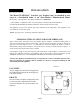
INSTALLATION The Model FP-BR10-ZC Vent-Free gas fireplace may be installed in any room in a Residential home or an After-Market* Manufactured Home. (Exception: This appliance may not be installed in a bathroom.) * (After Market: Completion of sale, not for the purpose of resale from the manufacturer). For After-Market Manufactured Home installation, check with state and local codes. This appliance is only for use with the type of gas indicated on the rating plate.
Fireplace and Framing Dimensions (ins.) 25 1/8” 11 5/8” 20 3/8” 24” 26 1/8” 26 1/8” GAS LINE 1 3/4” 8” 25 1/8” 13 1/2” FIGURE 2 WARNING:Installation and repairs should be performed by a qualified service person. The appliance should be inspected before use and at least annually by a professional service person. More frequent cleaning may be required due to excessive lint from carpeting, bedding material, etc.
FIREPLACE CLEARANCES depth. Alternatively, the carpeting, (vinyl) tile, etc. may be removed beneath the fireplace before installing. COMBUSTIBLE MATERIALS MUST NOT BE INSTALLED OVER OR TOUCH ANY BLACK PAINTED SURFACE. DO NOT BLOCK HEAT CIRCULATING AIR OUTLETS. DOING SO MAY RESULT IN POTENTIAL FIRE HAZARDS. 1. Sidewall Clearances: Clearances from the side of the fireplace opening to any adjacent combustible wall should not be less than 7". 2.
FINISHING YOUR FIREPLACE There is a wide variety of finishing material available for your fireplace from formal wall treatments with marble and mantels, to rustic wood paneling, stone or brick. Non-Combustible materials used in this installation such as slate, tile, marble, etc. must be at least 1/2" thick. IT IS IMPORTANT THAT THE BLACK FACE OF THE FIREPLACE NOT BE COVERED WITH ANY TYPE OF COMBUSTIBLE MATERIAL.
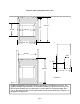
MANTEL PROFILES FOR ZERO CLEARANCE CABINET MUST BE FOLLOWED MANTELS WITH 3/4" BASE CEILING 12" 10" COMBUSTIBLE MATERIAL 3-1/2" COMBUSTIBLE MATERIAL 42" 3-1/2" 3/4" 3" 3/4" 3" 2-1/2" STAND OFF STAND OFF FP-BR10-ZC FP-BR10-ZC LOUVERS 2" LOUVERS 2" HOOD HOOD Bottom of 3/4" Base or Support must be at least 2-1/2" from top of Unit if mantel is 10" wide or more. Bottom of 3/4" Base or Support must be Flush with top of Unit if mantel is 10" wide or less.
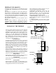
INSTALLATION OF MODEL FP - BR10- ZC WITH OPTIONAL WOODEN MANTEL (1) When choosing the right location for your heater and mantel keep the following in mind: NOTE: Due to high temperatures, this heater should be located out of traffic and away from furniture and draperies. NOTE: Kit No. (PA KDMH10) Deluxe Wooden Mantel for FP-BR10-ZC. Kit No.
TOP MANTEL 1/2" WOOD SCREWS (9) REAR OF HEATER MANTEL BASE FIGURE 6 Page 12
INSTALLATION AFTER-MARKET MOBILE HOMES THIS APPLIANCE MAY BE INSTALLED IN AN AFTERMARKET*, PERMANENTLY LOCATED, MANUFACTURED (MOBILE) HOME, WHERE NOT PROHIBITED BY LOCAL CODES. *After Market: Completion of sale, not for the purpose of resale from the manufacturer. THIS APPLIANCE IS ONLY FOR USE WITH THE TYPE OF GAS INDICATED ON THE RATING PLATE. THIS APPLIANCE IS NOT CONVERTIBLE FOR USE WITH OTHER GASES. NOTE: For mobile home installation follow “Installation”, pages 6-19.
PRODUCING ADEQUATE VENTILATION This section is for residential or manufactured (mobile) installation “This heater shall not be installed in a confined space or unusually tight construction unless provisions are provided for adequate combustion and ventilation air.” The National Fuel Gas Code, ANSI Z223.1/NFPA 54 defines a confined space as a space whose volume is less than 50 cubic feet per 1,000 BTU per hour (4.
DETERMINING FRESH-AIR FLOW FOR HEATER LOCATION DETERMINE IF YOU HAVE A CONFINED OR UNCONFINED SPACE Use this worksheet to determine if you have confined or unconfined space. SPACE: Includes the room in which you will install heater plus adjoining rooms with doorless passageways or ventilation grills between the rooms. 1. Determine the volume of the space (length x width x height). Length x Width x Height =_________cu.ft.(volume of space) EXAMPLE: 20 ft.(Length) x 16 ft.(Width) x 8 ft.
A. Rework worksheet, adding the space of an adjoining room. If the extra space provides an unconfined space, remove door to adjoining room or add ventilation grills between rooms. See “Ventilation Air From Inside Building”, page 21. B. Vent room directly to the outdoors. See “Ventilation Air From Outdoors”, page 22. C. Install a lower BTU/Hr heater, if lower BTU/Hr size makes room unconfined. If the actual BTU/Hr used is less than the maximum BTU/Hr the space can support, the space is an unconfined space.
VENTILATION AIR FROM OUTDOORS Provide extra fresh air by using ventilation grills or ducts. You must provide two permanent openings: one within 12" of the ceiling and one within 12" of the floor. Connect these items directly to the outdoors. These spaces include attics and crawl spaces. Follow the National Fuel Gas Code NFPA 54/ANSI Z223.1, Section 5.3, “Air For Combustion and Ventilation” for required size of ventilation grills or ducts.
GAS PRESSURE CHECK Check the inlet pressure to the burner to insure that it is as shown in the table below. NOTE: The pressure check point is located on the right side of the valve facing burner. The appliance and its appliance main gas valve must be disconnected from the gas supply piping system during any pressure testing of that system at test pressures in excess of 1/2 psi (3.5kPa).
LOG PLACEMENT Logs are shipped secured in unit. NOTE: When operated for the first time, logs may emit a “paper burning” smell. This smell will gradually diminish and will be totally eliminated after the first few hours of operation. Do not use the blower at this time. Front View of Logs WARNING “FAILURE TO POSITION THE PARTS IN ACCORDANCE WITH THESE DIAGRAMS OR FAILURE TO USE ONLY PARTS SPECIFICALLY APPROVED WITH HEATER MAY RESULT IN PROPERTY DAMAGE OR PERSONAL INJURY.
OPERATING INSTRUCTIONS Before operating this appliance, proceed through the following checklist . 1. Read and understand these instructions before operating this appliance. 2. Check that there no leaks. If you smell gas do not attempt to light this appliance. LIGHTING INSTRUCTIONS MODULATING VALVE(MAXITROL) FOR YOUR SAFETY, READ BEFORE LIGHTING WARNING IF YOU DO NOT FOLLOW THESE INSTRUCTIONS EXACTLY, A FIRE OR EXPLOSION MAY RESULT CAUSING PROPERTY DAMAGE, PERSONAL INJURY OR LOSS OF LIFE. A.
LIGHTING INSTRUCTIONS 1. 2. 3. 4. 5. 6. STOP! Read the safety information on the previous page. Make sure manual shutoff valve is fully closed. Open access panel door, located in lower front center of base for access to control knobs. Turn off all electric power to the appliance. Set thermostat (flame control) to lowest setting. Push in and turn control knob clockwise to the “OFF” position. PILOT ON 4 IGNITE OFF MERTIK 6 5 MAXITROL 7 3 2 1 FLAME CONTROL CONTROL KNOB FIGURE 3 7.
IGNITER ELECTRODE THERMO-COUPLE O.D.S PILOT BURNER PILOT 13. Close the access panel door. 14. “Turn on all electric power to the appliance.” CAUTION DO NOT TRY TO ADJUST HEATING LEVELS BY USING THE MANUAL SHUTOFF VALVE. TO TURN OFF GAS TO APPLIANCE SHUTTING OFF UNIT: Open access panel door, located in lower front center of base for access to control knobs. Set thermostat (flame control) to lowest setting. Turn control knob clockwise to the full “OFF” position.
THERMOSTAT CONTROL OPERATION The thermostat control used on this heater differs from standard thermostats. Standard thermostats simply turn the burner on and off. The thermostat used on this heater senses the room temperature and adjusts the amount of gas flow to the burner. This will increase or decrease the flame height. At times, the room may exceed the set temperature, which will cause the burner to shut off.
FLAME CHECK A periodic check of the flames should be made. The pilot flame should always be present when the gas logs are in operation. FLAME: Propane (LP) should produce a flame that is 3"-4" above rear log. This flame should be yellow. Natural gas should produce a flame that is 3"-4" above rear log. This flame should be mostly blue except for the top 1/2" which should be yellow.
WARNING: CHILDREN AND ADULTS SHOULD BE ALERTED TO THE HAZARDS OF HIGH SURFACE TEMPERATURE AND SHOULD STAY AWAY TO AVOID BURNS OR CLOTHING IGNITION. YOUNG CHILDREN SHOULD BE CAREFULLY SUPERVISED WHEN THEY ARE IN THE SAME ROOM WITH THE APPLIANCE. WARNING: DO NOT PLACE CLOTHING OR OTHER FLAMMABLE MATERIALS ON OR NEAR THE APPLIANCE.
WARNING: ELECTRICAL GROUNDING INSTRUCTION: THIS APPLIANCE IS EQUIPPED WITH A THREE-PRONG (GROUNDING) PLUG FOR YOUR PROTECTION AGAINST SHOCK HAZARD AND SHOULD BE PLUGGED DIRECTLY INTO A PROPERLY GROUNDED THREE-PRONG RECEPTACLE. NOTE: #PESBRO84 Blower Motor Rating: 120 volts/60HZ/0.54 Amps. 1 P.H NOTE: For convenience, allow licensed electrician to install properly grounded 3-plug receptacle near unit.
IMPORTANT SAFEGUARDS Although your gas logs are very realistic in appearance, it is not a real burning fireplace and must not be used for burning rejected material. • To avoid irreparable damage to the heater or personal injury, matches, paper, garbage, or any other material must not be placed or thrown on top of the logs or into the flames. • To avoid personal injury, do not touch hot surfaces when the heater is operating. • Close supervision is necessary when the heater is being operated near children.
TROUBLESHOOTING WARNING TURN OFF BURNER, UNPLUG HEATER AND LET COOL BEFORE SERVICING. ONLY A QUALIFIED SERVICE PERSON SHOULD SERVICE AND REPAIR HEATER. CAUTION NEVER USE A WIRE, NEEDLE, OR SIMILAR OBJECT TO CLEAN ODS/PILOT. THIS CAN DAMAGE ODS/PILOT. OBSERVED PROBLEM POSSIBLE CAUSE 1. Igniter button is pressed, no spark at ODS/Pilot 1. I g n i t e r electrode positioned incorrectly. 2. Igniter electrode broken 3. Igniter electrode not connected to igniter cable 4. Igniter cable pinched or wet 5.
5. Contact local propane gas company 6. Clean ODS/Pilot or 6. ODS/Pilot is clogged replace ODS/Pilot assembly 7. Replace gas regulator 7. Gas regulator setting is not correct 5. Depleted gas supply 3. ODS/Pilot lights but flame goes out when control knob is released 1. Control knob is not fully 1. Press control knob completely pressed in 2. Control knob not pressed 2. After ODS/Pilot lights keep control knob in long enough pressed 30 seconds 3. Safety interlock system 3.
6. Burner backfiring during combustion 1. Burner orifice is clogged or damaged 2. Burner damaged 3. Gas regulator defective 1. Clean burner (See “Cleaning and Maintenance “) or replace burner orifice 2. Replace Burner 3. Replace gas regulator 7. Slight smoke or odor during initial operation 1. Residues from manufacturing process 1. Problem will stop after a few hours of operation 8. Heater produces a whistling noise when burner is lit 1.
WARNING IF YOU SMELL GAS: * SHUT OFF GAS SUPPLY * DO NOT TRY TO LIGHT APPLIANCE * DO NOT TOUCH ANY ELECTRICAL SWITCH; DO NOT USE ANY PHONE IN YOUR BUILDING * IMMEDIATELY CALL YOUR GAS SUPPLIER FROM A NEIGHBOR’S PHONE. FOLLOW THE GAS SUPPLIER’S INSTRUCTIONS. * IF YOU CANNOT REACH YOUR GAS SUPPLIER, CALL THE FIRE DEPARTMENT. IMPORTANT: Operating heater where impurities in the air exist may create odors. Cleaning supplies, paint, paint remover, cigarette smoke, cements and glues, new carpet or textiles, etc.
SERVICING Repair and replacement work should only be performed by a qualified service technician. Always shut off the gas supply and make sure heater is cool before beginning any service operation. Check for gas leaks after servicing. REPAIR PARTS A parts list with exploded view follows. Always include correct name, part number, and model number of the heater when ordering service parts.
PARTS LIST Maxitrol Valve KEY # PART # DESCRIPTION 1 GV 30B5A2L7B Maxitrol LP Valve 1 1A GV 30B5A2N7B Maxitrol Nat. Valve 1 2 PE 4966 3/8" - 3/8" Elbow 1 3 PS 112736 Maxitrol Regulator Holder 1 4 PS 1024 BR 10 Burner Base 1 5 PO BR10 Burn Single Burner 1 6 PE TPT100/433 Thermo-couple/ (Copreci) 1 7 7A PE 21500053 PE 2150054 Copreci ODS Nat. Pilot Copreci ODS LP Pilot 1 1 8 8A PE RV12LF30 PE RV12LF90 Maxitrol Regulator-Nat.
BLOWN UP VIEW OF BURNER ASSEMBLY *16 Not shown on this page. See page 25, figure 10 for wiring diagram.
NEW BUCK CORPORATION We reserve the right to amend these specifications at any time without notice. The only warranty applicable is our standard written warranty. We offer no other warranty, expressed or implied. LIMITED WARRANTY MODEL FP-BR10-ZC New Buck warrants this product to be free from defects in materials and components for two (2) years from the date of first purchase, provided that the product has been properly installed, operated, and maintained in accordance with all applicable instructions.
Page 36