
Assembly Manual

HUB Assembly Manual 776-91-02-REV-.docx
THE INFORMATION CONTAINED HEREIN IS PROPRIETARY TO NEW CENTURION SOLUTIONS, INC. AND SHALL NOT BE REPRODUCED OR
DISCLOSED IN WHOLE OR IN PART FOR ANY DESIGN OR MANUFACTURE EXCEPT WHEN SUCH USER POSSESSES DIRECT, WRITTEN
AUTHORIZATION FROM NEW CENTURION SOLUTIONS, INC.
5
2. ASSEMBLY INSTRUCTIONS
To begin, check the parts available against the equipment list, identifying any missing
parts. If all parts are accounted for, proceed to the instructions below to begin
assembling the HUB.
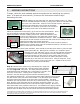
Step 1: Identify the two stand-offs (M) and four Phillips screws (H). Place
the two standoffs beneath the PCB (J), lining up the holes on the board with
the holes in the stand-offs. Insert a screw into both corners, effectively
attaching the stand-offs to the bottom of the board.
Flip the PCB over and line up the other two corners to
the existing screw holes on the bottom enclosure.
Follow the instructions on the Epoxy (Q) to mix the resin and hardener. Place
the mixed adhesive solution along the base of the stand-offs and press
against the bottom enclosure making a firm seal. When the adhesive is dry,
unscrew the PCB from the two stand-offs, which should
now be firmly attached to the bottom enclosure. After verifying, line up the
four corners so that each has a screw hole and insert the four Phillips screws
attaching the PCB to the bottom enclosure.
Note that the stand-offs can be offset (do not need to make a square in
respect to the existing screw holes on the bottom enclosure) as there are two
holes in each corner of the board.
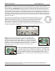
Step 2: Identify the three panel indicators, there should be two dark green LEDs (L) and one light
green/yellow LED (N). Although not necessary, the respective panel
indicator wires (red and black) can be cut to around half the length and
re-stripped in order to prevent against excessive folding of the wires
inside the enclosure as the wires are much longer than required.
Take the first indicator (order does not matter) and place a crimp
terminal (L) on the end of one of the wires. Using a crimp tool, crimp
the terminal into place on the end of the wire. Repeat for all six wires
attached to the three panel indicators.
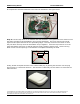
Step 3: Take the front enclosure (F) and identify the rough side
as opposed to the smooth side. Feed the three panel indicators
into the rough side, wires first. The front enclosure has three
small identical holes seperated into a single hole on one side, and
two holes on the other. Looking at the rough side of the
enclosure, the first dark green panel indicator should be fed into
the rightmost isolated hole. The light green/yellow panel indicator should be fed
into the closest of the two holes to the middle. The other dark green indicator
should be fed into the farther of the two holes from the middle. The panel
indicators will snap into place when they are pushed all the way into the holes.
Next, feed the crimp terminals into the 2 position connector header (C). The
terminals should be inserted into the end with the larger openings. Be sure to
take careful note of the positions of the wires. As indicated in the figure, with the
connector ears on the right, the red crimp wire should be inserted into the top
position while the black crimp wire should be inserted into the bottom position.
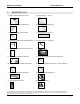
Step 1
Step 2
Step 3
Adhesive on
base of
stand-offs