
Assembly Manual

HUB Assembly Manual 776-91-02-REV-.docx
THE INFORMATION CONTAINED HEREIN IS PROPRIETARY TO NEW CENTURION SOLUTIONS, INC. AND SHALL NOT BE REPRODUCED OR
DISCLOSED IN WHOLE OR IN PART FOR ANY DESIGN OR MANUFACTURE EXCEPT WHEN SUCH USER POSSESSES DIRECT, WRITTEN
AUTHORIZATION FROM NEW CENTURION SOLUTIONS, INC.
6
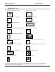
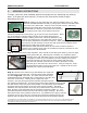
Step 4: Aquire the barrel jack connector (A), coaxial cable jack (G), and the 5 pin USB panel
mount cable (K). For both the barrel jack connector and the coaxial cable jack, feed the connector
ends through the smooth side of the front enclosure so that the connector ends are facing out
similar to the panel indicator LEDs. Additionally, be sure to fasten the respective washer and nut
(color matched) to the connector end so that both parts are firmly attached to the front panel. For
the USB cable, align the panel mount face with the front enclosure, matching up the screw holes
accordingly. Take the included screws and insert them into the two holes on both sides of the face.
Using a Phillips head screwdriver, fasten both nuts to the other side of front enclosure holding the
USB cable into place.
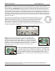
Next, take a red and a black wire, and strip both ends around a quarter inch (1/4”).
Facing the three pins on the barrel jack with no pin on top, the red wire should be
soldered to the rightmost pin (pin 1). The black wire should be soldered to the
bottom pin (pin 2) and no wire should be soldered to the leftmost pin (pin 3).
At this point six components should be firmly entrenches in the six holes on the
front enclosure. Please refer to the figure below and verify that all parts have been placed
correctly in the space provided for it.
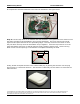
Step 5: Now that the front enclosure has been assembled, each
respective part can be attached to the PCB. The coaxial cable jack
attaches to the coaxial cable plug notated J1 on the board silkscreen.
The 5 pin USB panel mount cable attaches to the black 5 pin header
notated J3. When connecting the cable to the header it is important to
take note of the arrow designators on both components. The arrows
must match up on the same pin. Failure to do so may result in
damaged circuitry.
The barrel jack adapter attaches to the white 2 pin header designated as
P4. As a check, it should be verified that the red wire is assigned to the
+5V pin and the black wire is assigned to the GND pin. The isolated dark
green panel indicator attaches to the 2 pin header labeled P5. The light
green/yellow indicator nearest to the middle attaches to the middle
header labeled P7. The last dark green indicator attaches to the header
labeled P6.
J1
J3
P5
P7
P6
Step 4