
User's Manual


HUB Installation Manual 776-91-05-REV-A_HUB_INSTALLATION_MANUAL.docx
THE INFORMATION CONTAINED HEREIN IS PROPRIETARY TO NEW CENTURION SOLUTIONS, INC. AND SHALL NOT BE REPRODUCED OR
DISCLOSED IN WHOLE OR IN PART FOR ANY DESIGN OR MANUFACTURE EXCEPT WHEN SUCH USER POSSESSES DIRECT, WRITTEN
AUTHORIZATION FROM NEW CENTURION SOLUTIONS, INC.
6
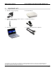
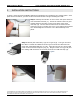
Step 3: Identify the HUB Power Supply (D). Plug the barrel jack plug into the mating barrel jack
on the front panel of the HUB assembly (B). Plug the U.L. approved power cord, 6 ft. length (F)
into the HUB Power Supply (D). Only one end will mate with it properly. Plug the other end of the
power cord into a standard 120 Volt wall outlet. The green light on the front panel of the HUB
should illuminate.
1 – Green status indicator light / yellow status
indicator light
2 – Flexible ½ wave center-fed dipole antenna
with articulated knuckle
3 – USB cable type-B end, plugged into the
HUB assembly
4 – Green power indicator light – this should
illuminate whenever the HUB is correctly
connected to a power source
5 – Barrel jack plug of HUB Power Supply (D),
plugged into the barrel jack of the HUB
assembly
3. FCC NOTIFICATION
NOTE: THE MANUFACTURER IS NOT RESPONSIBLE FOR ANY RADIO OR TV INTERFERENCE
CAUSED BY UNAUTHORIZED MODIFICATIONS TO THIS EQUIPMENT. SUCH MODIFICATIONS
COULD VOID THE USER’S AUTHORITY TO OPERATE THE EQUIPMENT.
THIS DEVICE COMPLIES WITH PART 15 OF THE FCC RULES. OPERATION IS SUBJECT TO THE
FOLLOWING TWO CONDITIONS: (1) THIS DEVICE MAY NOT CAUSE HARMFUL INTERFERENCE, AND
(2) THIS DEVICE MUST ACCEPT ANY INTERFERENCE RECEIVED, INCLUDING INTERFERENCE THAT
MAY CAUSE UNDESIRED OPERATION.