
Installation Manual


IREP Installation Manual 776-91-06-REV-A_IREP_INSTALLATION_MANUAL.docx
THE INFORMATION CONTAINED HEREIN IS PROPRIETARY TO NEW CENTURION SOLUTIONS, INC. AND SHALL NOT BE REPRODUCED OR
DISCLOSED IN WHOLE OR IN PART FOR ANY DESIGN OR MANUFACTURE EXCEPT WHEN SUCH USER POSSESSES DIRECT, WRITTEN
AUTHORIZATION FROM NEW CENTURION SOLUTIONS, INC.
5
2. INSTALLATION PREREQUISTIES
Ensure that the following installation prerequisite is met:
Wiring and installation of double-gang box
3. INSTALLATION INSTRUCTIONS
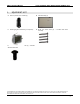
To begin, check the parts available against the equipment list, identifying any missing parts. If all
parts are accounted for, proceed to the instructions below to begin installing the IREP.
Step 1: Identify the Antenna, helical short ¼ wave (A). Screw the
antenna into the gold coaxial antenna connector on the top of the
IREP assembly (B). Ensure that the antenna is screwed onto the
connector snugly, but take care not to over-tighten the antenna as
it will damage the connector or the IREP assembly enclosure.
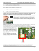
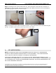
Step 2: Identify the power supply wires located within the double-gang installation. Ensure that
the positive and negative wires are identified before proceeding with the installation.
Identify the green and orange terminal block on the IREP Printed Circuit Board (PCB). Note the “+”
silkscreen market on the PCB just to the
lower right of the terminal block. Connect
the positive power supply wire to the
terminal block connection distinguished by
the “+” marker, and connect the negative
power supply wire to the opposite terminal
block connection.
The green LED on the front of the IREP
enclosure should illuminate when power is
correctly connected.
Type-A
(+)
(-)
Step 1
Step 2