
Assembly Manual

OREP Assembly Manual 776-91-04-REV-.docx
THE INFORMATION CONTAINED HEREIN IS PROPRIETARY TO NEW CENTURION SOLUTIONS, INC. AND SHALL NOT BE REPRODUCED OR
DISCLOSED IN WHOLE OR IN PART FOR ANY DESIGN OR MANUFACTURE EXCEPT WHEN SUCH USER POSSESSES DIRECT, WRITTEN
AUTHORIZATION FROM NEW CENTURION SOLUTIONS, INC.
7
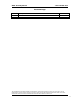
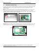
Step 5: Feed the wires from the panel receptacle into the terminal block labeled P1 on the PCB by
pushing down on one orange tab and feeding the wire through the respective terminal. Looking
down on the terminal block with the tabs on the right, the red wire should be inserted into the top
terminal and the black wire should be inserted into the bottom as indicated in the figure below.
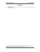
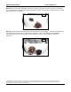
Step 6: Insert the pigtail connector end of the RF cable into the RF port labeled J1 on the PCB by
laying connector over the port and pressing down on the connector. The connector should snap
right into place.
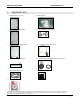
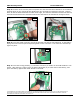
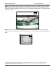
Step 7: Insert the Tenergy battery (J) connector into the 3 pin header on the PCB beside the “on”
switch. After doing so, apply a piece of double sided tape (K) to either side of the battery, and
press the battery against the metal shields on the PCB.
Step 5
Step 6
Step 7