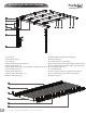
2 x 12 Flat Top Attached Louvered Pergola A S S E M B LY G U I D E Model: Elysium OPTIONAL ACCESSORIES: • Bolt Down Bracket Kit (2 for Pergola) Ver 1.0-113015 • Privacy Wall • Pergola Planter www.newenglandarbors.
Ta b l e o f Co n t e n t s PAGE 12 x 12 Flat Top Attached Louvered Pergola Introduction & Overview……………………………. . . . . . . . . . . . . . . . . . . . . . . . . . . . . . . . . . . . . . . . . . . . . . . .………. . . . . . 3 Pergola Materials Overview………………………. . . . . . . . . . . . . . . . . . . . . . . . . . . …. . . . . . . . . . . . . . . . . . . . . . . . . . . . . . . . . . . 4 Pergola Materials Breakdown………………………. . . . . . . . . . . . . . . . . . . . . . . . . . . . . . . . . . . . .…. . . . . . . .
IInnttrroodduuccttiioonn && O Ove verrvviieew w Getting Started First off, allow us to say thank you for the investment you have made in one of our fine pergola kits. This kit is designed to be assembled and installed ideally by two people with basic carpentry knowledge and tools. Do not attempt alone, especially during the installation stage.
Elysium Pergola Materials Overview www.newenglandarbors.com 1 2 3 4 9 7 10 20 6 5 8 13 12 11 1. 2. 3. 4. 5. 6. 7. 8. 9. 10. 11. One Way 4”x4 “ Internal Wood Post Guides (4) Post Caps (2) 12. Louver Turn Bar (1) Main Column Tops (2) 13. Turn Bar Holder (1) - Found in Box 7 Post Trims (4) 14. Pre-assembled Louver Bars (Right) - With Long Louver Bar (3) Rafter & Beam Decorative End Caps (12) 15.
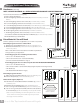
Elysium Pergola Materials Breakdown Check Boxes (Total of 7) for These Contents www.newenglandarbors.com In the event of missing or defective parts please call our customer service dept. at 1 800 282 9346 (Mon. to Fri. 8:00 AM to 4:00 PM EST). 1. Post Caps (2) 2. Main Column Tops (2) 3. Post Trims (4) 4. Rafter & Beam Decorative End Caps (12) 5. Main Support Beams (4) 6. Main Support Beams - Attached Side (With pre-drilled holes on top) (2) 7. Beam & Rafter Joiners (9) 8. Main Column Bottoms (2) 9.
Pergola Additional Materials List www.newenglandarbors.com Hardware (in plastic bag) NOTE: WE HAVE INCLUDED 10% EXTRA SCREWS BEYOND WHAT IS IDENTIFIED BELOW A All Screws Included with this Kit are Self-Auguring. BC FG H I J A. Tube of Vinyl Weld Glue (2) B. 5/8” Self-Auguring Stainless Steel Screws (72) (to lock Louver Assembly to Steel Holder Brackets ) C. 5/8” Self-Auguring Stainless Steel Screws (24) (to lock Rafter Hangers to Rafter) D.
Wood Post Layout & Installation for attached Pergola This pergola can also be installed on a pre-existing wood or concrete surface using our bolt down bracket system with a 4x4 wood post (sold separate). See page eight for more details. 1 Overhead View 136 3/8 in. 346.3 cm. Post location and placement is the most critical step in the overall installation process. Please double check for the possibility of any underground utilities such as sprinkler, gas or telephone lines.
OPTIONAL STEP 1 Wood Post Layout & Installation using Bolt Down Brackets for Concrete or Wood Surface for Attached Pergola * 135 3/4 in 344.9 cm 1 Measure and mark out the location of the bolt down brackets using string or chalk line. Adjust string lines accordingly. The inside corner of the string lines will be the corner of the bottom flange. * Orientate brackets accordingly to reduce offset motion of posts. (direction of arrows denote flange opening) Wall 2 134 3/8 in 341.
*Ensure that hole at top of column are orientated correctly for future beam and rafter placement. STEP THREE Vinyl Column Assembly & Installation Over Wood Posts 1 * Using the vinyl weld glue, insert the One Way 4”x4” Internal Wood Post Guide in the one end of the main column posts. This step is only applicable if your wood 4x4 post are embedded into the ground. If your pergola is going to be installed on wood or concrete surface, please dispose of these four pieces.
At this stage, the columns should be properly installed as per the following illustration, with the columns 134” in. (340.4 cm) apart. Critical: Note the opening direction of the holes on the top of the posts. 135 5/8 in. 344.4 cm. 134 in. 340.4 cm. STEP FOUR 1 Main Support Beam Assembly 1 Insert one 2x6x12 pressure treated wood into a beam followed by the joiner and another beam section. Critical Note: Note the location of the pre-drilled holes on the end of the main support beams.
STEP SIX www.newenglandarbors.com Main Support Beam Assembly for Attached Wall Side 1 Insert one 2x6x12 pressure treated wood into a beam followed by the joiner and another beam section. Pre-drilled holes at the top of the main support beam Critical Note: Note the location of the pre-drilled holes on the top of the main support beams. The cluster of four pre-drilled holes needs to be away from the jointer as shown. 2 Screw the joiner to vinyl beams and wood insert using 1 1/2” screws.
STEP SEVEN www.newenglandarbors.com Rafter Assembly 1 To accomodate the notches on the rafters, first the wood inserts must be cut down and notched out as shown below: 143 in 3 1/2 in 13 in (min) Six will be needed. 2 Insert one 2x6x12 pressure treated wood from the previous step into a beam followed by the joiner and another beam section. Note the orientation of the notch on the wood insert. 2 3 Screw the joiner to vinyl beams and wood insert using 1 1/2” screws. 4 Repeat for all six rafters.
2 1 STEP SEVEN Ledger Boards and Main Support Beam Placement Using a helper and two ladders proceed to complete the following steps: 1 Position and place the two main support beams onto both sides of the posts. 2 3 Fasten the two beams to the post by using the bolt assembly that comes with the hardware kit. You’ll need two wrenches to fasten the nuts and bolt. 3 Mount the two 2x6x6’ pressure treated wood pieces (sold separate) on your wall surface.
STEP EIGHT Main Support Beams & Rafter Placement Using a helper and two ladders proceed to complete the following steps: 1 1 Mount the main support beam which has the rafter hangers onto the wood beam as shown. The top of the wood beam should be flush with the top of the support beam. Fasten the main support beam attached to the wall so that it’s centered to the main support beams attached to the vinyl columns. To fasten, use a minimum of six 3½” lag screws through the main support beam and wood beam.
STEP NINE Fastening Pergola ends and Caps 1 Install decorative pergola end caps using vinyl weld. 2 Final position your post trims. 1 3 To glue decorative end caps place: 1. Apply a generous amount of vinyl glue to the decorative end caps as shown. 2. Slide the decorative end caps into the beam/rafter and allow a few minutes for glue to cure. To position post trim in place: 1. Slide the post trim down. 2. Apply a generous amount of vinyl glue around the post 3.
Pre-Assembled Louver Bars with Long Louver Bar STEP TEN Louver Assembly 1 This kit contains four different pre-assembled Louver Bars as shown below and aside: 3 x Pre-Assembled Louver Bars (plain) 6 x Pre-Assembled Louver Bars with Long Louver Bar* 3 x Pre-Assembled Louver Bars with Short Louver Bar Note the difference in distance to the first Louver Bracket *) There are two variations of Louver Bar Assemblies with Long Louver Bar.
Louver S T E P Assembly EIGHT 2 Insert the Louver Boards one by one. Make sure each board is inserted completely into the brackets. www.newenglandarbors.com 2 3 Attach the matching Pre-assembled Louver Bar. Pressure fit the boards one by one. 3 The ends of the louver bars with large space should be at the same end. 4 Ensure that the holes in the louver holder brackets are all on top of the louver bars assembly Repeat for all six sub-sections.
Louver Assembly www.newenglandarbors.com 5 Place twelve Steel Holder Brackets as shown below and carefully lower the Louver assembly onto the steel brackets. Do not screw the Steel Holder Brackets in place at this point. Steel Holder Brackets 6 Install in order (one row at a time) Fasten the Short Louver Bar using two nuts as shown. Do not over tighten. You will need to raise the middle section momentarily to do this step. Note: check that the holes are closer to the bottom as shown.
Louver Assembly 7 Slide the Steel Holder Brackets to a spot which will not interfere with the operations of the louvers. ‘Open’ and ‘Close’ the louvers to test and make sure the steel brackets are not constraining the operation. 8 From the top, fasten the steel brackets in place using 5/8” screws. A total of 12 screws will be needed. 9 Repeat for the underside of the steel brackets. Another 12, 5/8” screws will be needed. 8 9 Bottom View www.newenglandarbors.
Louver Assembly 10 www.newenglandarbors.com Repeat for other two rows. 10 11 Place the Post Caps onto the posts.
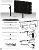
STEP ELEVEN www.newenglandarbors.com Turn Bar Holder Installation The Turn Bar Holder is packaged in box 7 kit and is designed to provide a place to keep the Turn Bar when not in use. 1 Pick a location that is easily accessible and out of the way of the louvers operation. The post is recommended as the 2 1/2” screws are used to protrude into the wooden post, providing a secure mounting support. 2 Mount with the slot on the top and closer to the post as shown. Fasten with two 2 1/2” screws provided.
O P E R AT I O N S 1 1 To adjust the positions of the louvers, slide the Turn Bar in between two louver boards and turn in a circular motion to the desired position. Excessive force should not be required. 2 For best leverage, push with the arm of the Turn Bar as opposed to ‘prying’ with the Turn Bar Cap(see illustrations). 3 If operation proves to be difficult, this may be caused by nut(s) that are too tight.