TRANSDUCTION USER’S MANUAL Version 1.
Table of Contents Important Information ............................................................... Warranty .................................................................................. Recommended Use ................................................................. i i ii Chapter 1 - Introduction Contents ...................................................................... TR-5001 Specifications ................................................ Driver Installation ............................
Important Information The information in this document is subject to change without notice. All relevant issues have been considered in the preparation of this document. Should you notice an omission or any questionable item in this document, please feel free to notify Transduction. Regardless of the foregoing statement, Transduction assumes no responsibility for any errors that may appear in this document nor for results obtained by the user as a result of using this product.
Recommended Use Safety Precautions and Maintenance FOR OPTIMUM PERFORMANCE, PLEASE NOTE THE FOLLOWING WHEN SETTING UP AND USING THE TR-5001-PM: DO NOT OPEN THE MONITOR. There are no user serviceable parts inside and opening or removing covers may expose you to dangerous shock hazards or other risks. Refer all servicing to qualified service personnel. Do not spill any liquids into the cabinet or use your monitor near water.
1 Introduction This chapter is designed to give you an overview on the TR-5001 industrial PC. The topics covered are as follows: Contents .................................................................... 2 TR-5001 Specifications ............................................. 3 Driver Installation ..................................................... 4 Touchscreen ..............................................................
Contents Your new TR-5001 box* should contain the following: • • • • TR-5001 PC/LCD Power Cord User’s Manual CD-ROM with drivers User’s Manual CD-ROM with drivers *Remember to save your original box and packing material to transport or ship the monitor.
TR-5001 Specifications Model Processor TR-5001 NEMA 4 Panel Mount and Rack Mount Industrial PC with TFT LCD Touch Screen Intel Socket 478 for Pentium 4 or Celeron up to 3.
Driver Installation The Driver CD will auto-run when inserted in the CDROM drive. It will detect and select your single board computer and will help you to install the drivers automatically. Install Related Chipset INF Driver The selection helps you to install the INF of related chipset interface. Install VGA Driver The selection helps you to install the driver of the on-board VGA interface. Install LAN Driver The selection helps you to install the driver of the on-board LAN interface.
Touchscreen USB Controller Driver Installation All Windows drivers are included on the Transduction TR-5001 8-wire Touchscreen Drivers CD along with Troubleshooting. NOTE: For Win XP and 2000 you MUST logon with administrator’s password. TouchKit software on the driver CD has the required drivers and the utility for toggling between left and right mouse buttons and configuration support. These will all be installed when Setup.exe is run from the CD.
Advanced A 25 Point calibration utility for the touch sensor. Press Clear to clear previous calibration records. Press 25 pts Cal to do 25 point calibration by touching the blinking symbol on the panel until you get a beep or it stops blinking. After calibration, the new record will overwrite the old one. 2. SETTING: Sound, Mouse Mode and Double Click Adjustment Sound No Sound Choose to make no sound when panel is touched. Touch Down Beep will sound when panel is touched.
Mouse Mode The Mouse Mode provides users different operating options. Mouse Button Click it to show/hide Touch Tray on the right bottom corner of the desktop. Users can choose show or hide Touch Tray from the mouse icon in the taskbar. Change right/left button by clicking the upper small rectangular box of Touch Tray. Blue area indicates which button has been selected.
Mouse Mode There are three mouse modes: [Normal Mode] Provides all the mouse functions, including the dragging function. [Click on Touch] Click action is executed as soon as panel is touched. [Click on Release] Click action will not be executed until finger leaves the panel. Option Touchkit provides an option for advanced Mouse Emulation setting. When the Option button is pressed, a setting property sheet will pop up.
Double Click Speed Double Click Speed is the double click response time for the Windows system. Users can adjust the speed for easy double click by touch panel. Double Click Area Each individual touch has its own touch tolerance. If the Double Click Area is set to , the panel will be very sensitive about micro-movements when you want to fix on a point. If set to , larger touch point movement is tolerated when you want to point at a fixed position. 3.
In some cases, the cursor will be behind the finger when you touch the panel. If you cannot see the cursor, you can set the X Axis or Y Axis to move the cursor. Offset X Axis If you set the Offset X Axis to , cursor will be moved one pixel to the left of the X Axis. If you set the Offset X Axis to , cursor will be moved one pixel to the right of the X Axis. Offset Y Axis If you set the Offset Y Axis to , cursor will be moved one pixel above the Y Axis.
Set the check box (Use Multiple Monitors) to enable multiple monitors mapping. Unchecking this box will disable multiple-monitor configuration, and all of the touch panel controllers will be mapped to the primary monitor. The gray shadow area is the monitor mapped to the selected controller/panel. The button [Mapping] is used to find the mapping relationships between the monitors and touch panel controllers.
Declaration of the Manufacturer We hereby certify that the TR-5001 is in compliance with UL cUL TUV FCC CE TRANSDUCTION 5155 Spectrum Way Bldg 23 Mississauga, ON L4W 5A1 Canada 905-625-1907 www.transduction.
2 TR-979 SBC Introduction This chapter provides information on the TR-5001 single board computer, TR-979 . The topics covered are: Checklist ..................................................................... 14 Description ................................................................. 14-15 Features ........................................................................ 16 Specifications ...............................................................
Checklist Please check that your package is complete and contains the items below. If you discover damaged or missing items, please contact your dealer.
SATA-150 ports with RAID 0 and 1 support, high performance serial ports, enhanced parallel port, and the most updated BIOS. Four USB 2.0 ports and a programmable watchdog timer are available on-board. What’s more, the Intel 865G on-board incorporates the latest microprocessor technology to provide the increased bandwidth needed to operate your system bus at speeds up to 800MHz FSB.
Features Support Pentium 4 Prescott (90nm) and Northwood(0.13um) CPU with 400/533/800M FSB speed selectable. Intel VRD 10.1 compliant to support future advanced processor. Dual Channel Memory bus doubles the data rate, up to 6.4GBytes/s. System memory speed can be DDR266,330 or 400, selectable by BIOS setup. Dual SATA ports with classic IDE, RAID0 or RAID 1 mode configurable. Rebuild supported at RAID 1 mode with Intel IAA software.
Specifications • 17 Processor Socket 478 supports Intel® Pentium® 4 series processors: Intel® Celeron® based on 0.13μcore, 400MHz FSB, up to 2.80GHz Intel® Pentium® 4 based on 0.13μcore, 512KB L2, 533MHz FSB, without HT Technology, up to 2.80 GHz Intel® Pentium® 4 based on 0.13μcore, 512KB L2, 533MHz FSB, with HT Technology, up to 3.06 GHz Intel® Pentium® 4 based on 0.13μcore, 512KB L2, 800MHz FSB, with HT Technology, up to 3.
PIDE and SATA: Two Enhanced PIDE interfaces for up to four devices, support PIO Mode 3/4 or Ultra ATA33/66 /100 IDE Hard Disk, ATAPI CD-ROM and LS-120 drive. Two SATA connectors support up to two SATA-150 HDDs. Two SATA ports can be configured as RAID-0 and RAID-1 with RAID BIOS and Intel IAA drivers. SATA RAID BIOS is integrated in System BIOS. • FDD Interface: Two floppy drives (360KB, 720KB, 1.2MB, 1.44MB, 2.
• Audio: RealTek ALC201A AC97 Audio chip on-board. One 10-pins pin-haeder for Audio Line-IN, Line-OUT and MIC cabling. One CD-ROM Audio-In 4-pins connector on-board. • BIOS: Phoenix-Award Standard PnP BIOS 6.2. 19 4Mbit FlashROM with BootBlock for Fail-safe. Enhanced ACPI and DMI2.0 compliant. BIOS utility for field update. VBIOS and LAN remote Boot Agent integrated. 32-pins PLCC type socket for easy field replacement. • ISA and PCI Expansion Slot: Full-Size PICMG 2.
ATX Power Supply support: • On-borad 4-pin ATX power supply header (requires the passive backplane supports ATX power supply) On-board power button header for Soft power off, i.e. front panel turn off system power. Support Windows2K/XP shutdown automatically turn off the system power. Instant-off or delay-4-seconds selectable via BIOS setup. Hardware Monitor System: • PC Health Monitoring ASIC supports system power voltages, FAN speed and system temperatures monitoring.
3 Installations This chapter provides information on how to use the jumpers and connectors on the TR-979 in order to set up a workable system. The topics covered are: CPU Installation ..................................................................... 22 Memory Installation ............................................................... 23 Jumpers on the TR-979........................................................... 24-29 Connectors on the TR-979......................................................
CPU Installation The TR-979 Industrial SBC Card provides a 478-pins ZIF socket for Pentium 4 processors with FC-PAG2 package. To Install a CPU, first turn off your system and remove its cover. Locate the ZIP socket and open it by first pulling the lever sideways away from the socket then upwards to a 90-degree right angle. Insert the CPU with the correct orientation. Use the notched corner of the CPU with the white dot as your guide. The white dot should point towards the end of the lever.
Memory Installation The TR-979 Industrial CPU Card provides two 184-pin DIMM sockets for a maximum total memory of 2GB SDRAM. The memory modules can come in sizes of 128MB, 256MB, 512MB and 1GB SDRAM. The TR-979 Industrial CPU Card supports two 184-pin DIMM (Dual In-line Memory Module) sockets. In populating the DIMM sockets, DIMM1 bank should be populated first for less signal reflection. However, we do not see any issue while populate DIMM2 only.
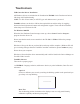
Jumpers on the TR-979 The jumpers on the TR-979 allow you to configure your SBC card according to the needs of your applications. If you have doubts about the best jumper configuration for your needs, contact your dealer or sales representative. The following picture below shows the jumpers on TR-979 and their respective functions.
Jumper Locations on the TR-979 JP8 COM2MODE 25 JP9 TR-5001 User Manual
JP1 ~ 2: CPU Frequency Selector JP1 and JP2 allow users to select the CPU FSB speed. It can be 400MT/s, 533MT/s or 800MT/s. User should select the correct FSB speed to make their CPU run on correct speed and ensure the system runs stably.
JP4 ,JP5: WatchDog Timer Period Selection The WatchDog Timer time-out period can be set as 10 sec, 20 sec, 30 sec and 80 sec. The following table describes the jumper settings for the period. JP4 JP5 Time-out Period 10 Sec JP5 JP4 20 Sec JP5 JP4 30 Sec JP5 JP4 80 Sec JP5 JP4 JP6: WatchDog Timer Mode Selection The WatchDog Timer is enabled by reading I/O port 843H.
JP7: LCD PANEL Power Selection JP7 can be used to select the Panel LCD supple power: +3.3V or +5V. The default setting is on +3.3V.User need to check the LCD panel spec and adjust this jumper and make Panel work in specified power rail. +3.3V +5V JP8~ 9: On-Board LAN Enable/Disable selection On-Board Fast Ethernet LAN chips can be disabled by shorting the JP8 or/and JP9 jumper.
COM2MODE: COM2 RS232/RS422/RS485 Selection COM2MODE 17 1 I/F TYPE RS-232 18 17 2 1 RS-422 18 17 2 1 RS-485 18 29 2 TR-5001 User Manual
Connectors on the TR-979 The connectors on the TR-979 allows you to connect external devices such as keyboard, floppy disk drives, hard disk drives, printers, etc. The following picture below lists the connectors on TR-979.
Connector Locations on the TR-979 VGA IRDA LAN1 LAN1LED LAN2LED LAN2 COM2 COM1 Printer Floppy PS2KBMS ATKB CDIN SATA1 AUDIO USB1*2 USB3*4 IDE1 IDE2 SATA2 SYSFAN ATXPW LVDS WOL ATPWR Front Panel Keylock 31 CPUFAN TR-5001 User Manual
Front Panel Connector The front panel of the case has a control panel, which provides light indication of the computer activities and switches to change the computer status. RESET PWR HDD PWR LED LED BTN ¾ RESET Switch The reset switch allows the user to reset the system without turning the main power switch Off and then On. Orientation is not required when making a connection to this header.
¾ IDE Hard Disk LED Connector This connector connects to the hard drive activity LED on control panel. This LED will flash when the HDD is being accessed. IDE LED Signal Name Pin # IDE LED ¾ 5 6 IDE_ACT Ground ATX Power ON/OFF Button This 2-pin connector acts as the “Power Supply On/Off Switch” on the SBC card. When pressed, the switch will force the SBC card to power on. When pressed again, it will force the SBC card to power off.
EIDE Connectors Primary IDE Connector Signal Name Pin # Reset IDE Host data 7 Host data 6 Host data 5 Host data 4 Host data 3 Host data 2 Host data 1 Host data 0 Ground DRQ0 Host IOW Host IOR IOCHRDY DACK0 IRQ14 Address 1 Address 0 Chip select 0 Activity 34 1 3 5 7 9 11 13 15 17 19 21 23 25 27 29 31 33 35 37 39 Pin # Signal Name 2 4 6 8 10 12 14 16 18 20 22 24 26 28 30 32 34 36 38 40 Ground Host data 8 Host data 9 Host data 10 Host data 11 Host data 12 Host data 13 Host data 14 Host data 15 Key Groun
Secondary IDE Connector Signal Name Pin # Pin # Reset IDE Host data 7 Host data 6 Host data 5 Host data 4 Host data 3 Host data 2 Host data 1 Host data 0 Ground DRQ1 Host IOW Host IOR IOCHRDY DACK1 IRQ15 Address 1 Address 0 Chip select 0 Activity 35 1 3 5 7 9 11 13 15 17 19 21 23 25 27 29 31 33 35 37 39 2 4 6 8 10 12 14 16 18 20 22 24 26 28 30 32 34 36 38 40 Signal Name Ground Host data 8 Host data 9 Host data 10 Host data 11 Host data 12 Host data 13 Host data 14 Host data 15 Key Ground Ground Ground
Floppy Drive Connector Floppy connector is a 34-pin header and will support up to 2.88MB floppy drives.
Parallel Port Connector The following table describes the pin out assignments of this connector.
COM1 Serial Port COM1, a 10-pin header connector , is the onboard COM1 serial port of the TR-979. The following table shows its pin assignments. Pin # Signal Name 1 2 3 4 5 6 7 8 9 10 DCD, Data carrier detect RXD, Receive data TXD, Transmit data DTR, Data terminal ready GND, ground DSR, Data set ready RTS, Request to send CTS, Clear to send RI, Ring indicator N.C. COM2 Serial Port COM2, a 10-pin header connector, is the onboard COM2 serial port of the TR-979.
External Keyboard Connector 1 Pin # Signal Name 1 2 3 4 Keyboard clock Keyboard data PG GND 5 +5V PS/2 Keyboard & Mouse Connector The following table describes the pin assignment of PS/2 Keyboard and Mouse connector, which is mount on button of bracket. To attach PS/2 Keyboard and mouse, users need to connect trough a PS/2 1-to-2 Y-cable and plug into this Mini-Din connector. All the TR-979 SBC boards come with a Y-cable. Contact your dealer if the Y-cable is missing.
VGA Connector The pin assignments of VGA CRT connector are as follows: Signal Name Pin Pin Signal Name Red Blue GND GND N.C. N.C. HSYNC NC 1 3 5 7 9 11 13 15 2 4 6 8 10 12 14 Green N.C. GND GND GND N.C. VSYNC CPU Fan Power Connector This is a 3-pin header for the CPU fan. The fan must be a 12V fan. 1 2 3 Pin # Signal Name 1 2 3 Rotation +12V Ground USB Connectors The following table shows the pin outs of the USB connectors.
IrDA Connector This connector is used for an IrDA connector for wireless communication. +5V IRRX IRTX FIR IrDA Pin # Signal Name 1 2 3 4 5 +5V FIR Ir RX Ground Ir TX GND ATX Power Connector This is a four-pin connector to support the ATX power and corresponding back-plane. When your back-plane is configured to perform ATX power supply Soft-on/off function, you have to connect the control signals and stand-by power on this connector to your back-plane by a corresponding cable.
LAN- RJ45 Connector This connector is for the 10/100Mbps Ethernet capability of the CPU card. The figure below shows the pin out assignments of this connector and its corresponding input jack. Pin # Signal Name 1 2 3 4 5 6 7 8 MDI0+ MDI0MDI1+ MDI1MDI2+ MDI2MDI3+ MDI3- LAN LEDs The LAN LEDs on top of RJ45 are to display the current network connection status. The green color LED on the right-hand side shows the link status and TX/RX activity.
LANLED Connectors The 4-pins LANLED connector designed for each LAN port is for applications need to display LAN port status on front panel or the places administrators are easy to access. 4 1 LAN LED LAN LED Pin # Signal Name 1 2 3 4 ACTLEDLINKLEDORGLEDGRNLED- AT Power P8 Connector The following table describes the pin assignment of on-board AT Power P8 connector. This connector is for the applications which do not require a backplane.
CD_IN Connectors CD_INconnector is designed for wire the CD_ROM audio signals to the on-board Audio CODEC.
LCD LVDS Connector LCD LVDS connector is designed for wiring the LVDS signals to the LCD Panel. Signal Name TX0+ GND TX1+ TX2+ GND TX3+ GND TXC+ LCD_VCC 12V Pin # Pin # 1 3 5 7 9 11 13 15 17 19 2 4 6 8 10 12 14 16 18 20 Signal Name TX0GND TX1TX2GND TX3GND TXCLCD_VCC 12V Note: Contact your dealer for LCD Cable kit and Video BIOS customization.
Watchdog Timer Configuration The function of the watchdog timer is to reset the system automatically and is defined at I/O port 0843H. To enable the watchdog timer and allow the system to reset, read I/O port 0443H. To disable the timer, read I/O port 043H for the system to stop the watchdog function. The timer has a tolerance of 20% for its intervals. The following describes how the timer should be programmed.
4 BIOS Configuration This chapter describes the different settings available in the Award BIOS that comes with the TR-979 CPU card. The topics covered in this chapter are as follows: BIOS Introduction .................................................................. 48-50 Main Menu ............................................................................. 51-52 Standard CMOS Setup ........................................................... 53-57 Advanced BIOS Features ..................................
BIOS Introduction This Chapter discusses Award™ Setup program built into the TR-979 BIOS. The Setup program allows users to modify the basic system configuration. This special information is then stored in battery-backed RAM so that it retains the Setup information when the power is turned off. The AwardBIOS™ installed in TR-979 SBC is a custom version of an industry standard BIOS. This means that it supports Intel PentiumIV in a standard IBM-AT compatible input/output system.
do not press the keys at the correct time and the system does not boot, an error message will be displayed and you will again be asked to... PRESS F1 TO CONTINUE, DEL TO ENTER SETUP Using Setup In general, you use the arrow keys to highlight items, press to select, use the PageUp and PageDown keys to change entries, press for help and press to quit. The following table provides more detail about how to navigate in the Setup program using the keyboard.
Getting Help Press F1 to pop up a small help window that describes the appropriate keys to use and the possible selections for the highlighted item. To exit the Help Window press or the F1 key again. In Case of Problems If, after making and saving system changes with Setup, you discover that your computer no longer is able to boot, the AwardBIOS™ supports an override to the CMOS settings which resets your system to its defaults. The best advice is to only alter settings that you thoroughly understand.
Main Menu Once you enter the AwardBIOS™ CMOS Setup Utility, the Main Menu will appear on the screen. The Main Menu allows you to select from several setup functions and two exit choices. Use the arrow keys to select among the items and press to accept and enter the sub-menu.
Advanced Chipset Features Use this menu to change the values in the chipset registers and optimize your system's performance. Integrated Peripherals Use this menu to specify your settings for integrated peripherals. Power Management Setup Use this menu to specify your settings for power management. PnP / PCI Configuration Use this menu to set up the PnP/PCI configuration. PC Health Status Use this menu to display the CPU temperature, FAN speed and voltages.
Standard CMOS Setup The items in Standard CMOS Setup Menu are divided into 10 categories. Each category includes no, one or more than one setup items. Use the arrow keys to highlight the item and then use the or keys to select the value you want in each item.
This table shows the selections that you can make on the Standard CMOS Menu Item Date Description DD YYYY Time IDE Channel 0 Master HH : MM : SS Options are in its sub menu IDE Channel 0 Slave Options are in its sub menu IDE Channel 1 Master Options are in its sub menu IDE Channel 1 Slave Options are in its sub menu Drive A Drive B Base Memory None 360K, 5.25 in 1.2M, 5.25 in 720K, 3.5 in 1.44M, 3.5 in 2.88M, 3.
Channel 0 HDDs / Channel 1 HDDs The IDE adapters control the hard disk drive. Use a separate sub menu to configure each hard disk drive. Figure 2 shows the IDE primary Phoenix – AwardBIOS CMOS Setup Utility IDE Cannel 0 Master IDE HDD Auto-Detection [Press Enter] IDE Channel 0 Master Access Mode [Auto] [Auto] Capacity 0 MB Cylinder Head Precomp Landing Zone Sector 0 0 0 0 0 Item Help Menu Level ¾¾ To auto-detect the HDD’s size, head...
Item IDE HDD Auto-detection Options Press Enter IDE Channel 0 Master None Auto Manual Capacity Auto Display your disk drive size Access Mode Description Press Enter to auto-detect the HDD on this channel. If detection is successful, it fills the remaining fields on this menu. Selecting ‘manual’ lets you set the remaining fields on this screen. Selects the type of fixed disk. "User Type" will let you select the number of cylinders, heads, etc.
Drive A / Drive B These fields identify the types of floppy disk drive A or drive B that has been installed in the computer. The available specifications are: Non 360KB 1.2MB 720KB 1.44MB 2.88MB 5.25 in. 5.25 in. 3.5 in. 3.5 in. 3.5 in. Video This field selects the type of video display card installed in your system. You can choose the following video display cards: EGA/VGA For EGA, VGA, SEGA, SVGA or PGA monitor adapters. (default) CGA 40 Power up in 40 column mode. CGA 80 Power up in 80 column mode.
Advanced BIOS Features This section allows you to configure your system for basic operation. You have the opportunity to select the system’s default speed, boot-up sequence, keyboard operation, shadowing and security.
CPU Feature Phoenix – AwardBIOS CMOS Setup Utility Delay Prior Thermal Thermal Management Limit CPUID MaxVal CPU Feature [16Min] Thermal Monitor 1 [Disabled] Item Help Menu Level ¾ ↑↓←→Move Enter: Select +/-/PU/PD: Value F10:Save ESC: Exit F1:General Help F5:Previous Values F6:Fail-safe defaults F7:Optimized Defaults Delay Prior Thermal The choice: 4Min, 8Min, 16Min, 32Min. Thermal Management Limit CPU MaxVal Set Limit CPUID MaxVal to 3, Should Be “Disabled” for WinXp.
Hard Disk Boot Priority Phoenix – AwardBIOS CMOS Setup Utility Hard Disk Boot Priority 1. Bootable Add-in Cards Item Help Menu Level ¾ Use <↑> or <↓> to select a device, then press <+> to move it up, or <-> to move it down the list.
Hyper-Threading Technology Enabled Disabled For windows XP and Linux 2.4.x (OS optimized for Hyper Threading Technology) For other OS (OS not optimized for Hyper Threading Technology) Quick Power On Self Test Allows the system to skip certain tests while booting. This will decrease the time needed to boot the system. Enabled Disabled Enable quick POST Normal POST First/Second/Third/Other Boot Device The BIOS attempts to load the operating system from the devices in the sequence selected in these items.
Gate A20 Option Select if chipset or keyboard controller should control GateA20. Normal Fast A pin in the keyboard controller controls GateA20 Lets chipset control GateA20 Typematic Rate Setting Key strokes repeat at a rate determined by the keyboard controller. When enabled, the typematic rate and typematic delay can be selected. The choice: Enabled/Disabled. Typematic Rate (Chars/Sec) Sets the number of times a second to repeat a key stroke when you hold the key down.
APIC Mode MPS Version Control For OS The choice: 1.1, 1.4. OS Select For DRAM > 64MB Select the OS2 only if you are running OS/2 operating system with greater than 64MB of RAM on the system. The choice: Non-OS2, OS2. Report No FDD For WIN 95 This option allows Windows 95 to share with other peripherals IRQ6 which is assigned to a floppy disk drive if the drive is not existing. The default setting is No. The choice: Yes, No. Small Logo (EPA) show The choice: Enabled/Disabled.
Advanced Chipset Features Phoenix – AwardBIOS CMOS Setup Utility Advanced Chipset Features DRAM Timing Selectable x CAS Latency Time x Active to Precharge Delay x DRAM RAS# to CAS# Delay x DRAM RAS# Precharge Memory Frequency For System BIOS Cacheable Video BIOS Cacheable Memory Hole At 15M-16M AGP Aperture Size (MB) Init Display First [By SPD] [2.
DRAM Timing Selectable This item allows you to select the DRAM timing determined by the timing information stored in SPD or set by the User manually. The default is By SPD. When this field is set as By SPD, the DRAM Timing items below will become read-only. The choice: By SPD, Manual. CAS Latency Time When synchronous DRAM is installed, the number of clock cycles of CAS latency depends on the DRAM timing. Do not reset this field from the default value specified by the system designer. The choice: 3, 2.
Memory Frequency For This item allows user to set the DDR DRAM operation frequency. The Auto is default. The choice: DDR266, Auto. System BIOS Cacheable Selecting Enabled allows caching of the system BIOS ROM at F0000h-FFFFFh, resulting in better system performance. However, if any program writes to this memory area, a system error may result. The choice: Enabled, Disabled. Video BIOS Cacheable Selecting Enabled allows caching of the Video BIOS ROM, resulting in better system performance.
Init Display First The choice: PCI Slot, Onboard/AGP On-Chip VGA Setting On-Chip VGA The choice: Enabled, Disabled. On-Chip Frame Buffer Size The choice: 1MB, 8MB, 16MB. Boot Display The choice: Auto, CRT, LFP, CRT+LFP, EFP, TV, CRT+EFP, CRT+TV. Panel Number The choice: 1, 2, 3, 4, 5, 6, 7, 8, 9, 10, 11, 12, 13, 14, 15, 16.
Integrated Peripherals Phoenix – AwardBIOS CMOS Setup Utility Integrated Peripherals OnChip IDE Device Onboard Device SuperIO Device [Press Enter] [Press Enter] [Press Enter] Item Help Menu Level ¾ ↑↓←→ Move Enter: Select +/-/PU/PD: Value F10:Save ESC: Exit F1:General Help F5:Previous Values F6:Fail-safe defaults F7:Optimized Defaults OnChip IDE Device Phoenix – AwardBIOS CMOS Setup Utility OnChip IDE Device IDE HDD Block Mode IDE DMA transfer access On-Chip Primary PCI IDE IDE Primary Master PIO IDE
IDE HDD Block Mode If your IDE hard drive supports block mode select Enabled for automatic detection of the optimal number of block read/writes per sector the drive can support The choice: Enabled, Disabled. IDE DMA transfer acess The choice: Enabled, Disabled. On-Chip Primary PCI IDE The chipset contains a PCI IDE interface with support for two IDE channels. Select Enabled to activate the primary IDE interface. Select Disabled to deactivate this interface The choice: Enabled, Disabled.
Primary/Secondary Master/Slave UDMA Ultra DMA/33/66/100 implementation is possible only if your IDE hard drive and cable supports it and the operating environment includes a UDMA driver If your hard drive and your system software both support Ultra DMA/33/66/100, select Auto to enable BIOS support. The System BIOS will also check the IDE cable. Only if the 80-way ATA66/100 cable is installed, the ATA66/100 models can be enabled by the OS driver. Otherwise, the system will be limited to run up to ATA33 mode.
Onboard Device Phoenix – AwardBIOS CMOS Setup Utility Onboard Device USB Controller USB 2.
USB Mouse Support The choice: Enabled, Disabled. AC97 Audio The choice: Auto, Disabled. CSA LAN(Giga-LAN) The choice: Enabled, Disabled.
Onboard Serial Port 1/Port 2 Select an address and corresponding interrupt for the first and second serial ports. The choice: 3F8/IRQ4, 2F8/IRQ3, 3E8/IRQ4, 2E8/IRQ3, Disabled, Auto. UART Mode Select The choice: IrDA, ASKIR, Normal. RxD, TxD Active This item allows you to choose Hi-Active or Low-Active of TX and RX signlal, which depends on different H/W requirement.
EPP Mode Select Select EPP port type 1.7 or 1.9. The choice: EPP1.7, 1.9. ECP Mode Use DMA Select a DMA channel for the parallel port for use during ECP mode. The choice: 3, 1. PWRON After PWR-Fail The choice: Off, On, Former-Sts.
Power Management Setup The Power Management Setup allows you to configure you system to most effectively save energy while operating in a manner consistent with your own style of computer use.
ACPI Function This item allows you to enable/disable the Advanced Configuration and Power Management (ACPI). The choice: Enabled, Disabled. Power Management This category allows you to select the type (or degree) of power saving and is directly related to the following modes: 1. HDD Power Down 2. Suspend Mode There are three selections for Power Management, three of which have fixed mode settings. Disable (default) Min. Power Saving Max. Power Saving User Defined No power management.
Video Off In Suspend This determines the if the turn off the video display when system enter suspend mode. The choice: Yes, No. MODEM Use IRQ This determines the IRQ in which the MODEM can use. The choice: 3, 4, 5, 7, 9, 10, 11, NA. Suspend Mode When enabled and after the set time of system inactivity, CPU will be put into the suspend mode. The choice: Disabled, 1 min, 2 min, 4 min,8min, 12min, 20min, 30min, 40min, 1 hour.
Power On By Ring An input signal on the serial Ring Indicator (RI) line (in other words, an ncoming call on the modem) awakens the system from a soft off state. The choice: Enabled, Disabled. Wake Up On LAN The choice: Enabled, Disabled. Resume by Alarm When Enabled, your can set the date and time at which the RTC (real-time clock) alarm awakens the system from Suspend mode. The choice: Enabled, Disabled.
PnP/PCI Configuration Setup This section describes configuring the PCI bus system. PCI, or Personal Computer Interconnect, is a system which allows I/O devices to operate at speeds nearing the speed the CPU itself uses when communicating with its own special components. This section covers some very technical items and it is strongly recommended that only experienced users should make any changes to the default settings.
The choice: Enabled, Disabled. Resource controlled by BIOS can automatically configure all the boot and Plug and Play compatible devices. If you choose Auto, you cannot select IRQ DMA and memory base address fields, since BIOS automatically assigns them. The choice: Auto(ESCD), Manual. IRQ Resources When resources are controlled manually, assign each system interrupt a type, depending on the type of device using the interrupt.
- Bus 0 Dev31 Func 6 SMBus Cntrlr - Bus 0 Dev31 Func 3 Choices are Auto, 3, 4, 5, 7, 9, 10, 11, 12, 14, 15. INTC Assignment Device(s) using this INT: Network Cntrlr-Bus 1 Dev 1 Func 0 USB 1.0/1.1 UHCI Cntrlr -Bus 0 Dev29 Func 2 Choices are Auto, 3, 4, 5, 7, 9, 10, 11, 12, 14, 15. INTD Assignment Device(s) using this INT: USB 1.0/1.1 UHCI Cntrlr-Bus 0 Dev29 Func 1 Choices are Auto, 3, 4, 5, 7, 9, 10, 11, 12, 14, 15. INTE Assignment Choices are Auto, 3, 4, 5, 7, 9, 10, 11, 12, 14, 15.
PC Health Status This section helps you to get more information about your system including CPU temperature, FAN speed and voltages. It is recommended that you contact with your motherboard supplier to get proper value about your setting of the CPU temperature.
CPU FAN Speed Shows CPU FAN speed. CHASSIS FAN Speed Shows System FAN speed. Vcore/1.5V/3.3V/5V/12V/-12V/-5V/VBAT/5VSB Voltages Shows Power rails voltage. Shutdown Temperature Select the CPU over-heated shutdown temperature. The choice: Disabled, 60°C/140°F, 65°C/149°F, 70°C/158°F, 75°C/167°F.
Frequency/Voltage Control Phoenix – AwardBIOS CMOS Setup Utility Frequency/Voltage Control CPU Clock Ratio Auto Detect PCI Clk Spread Spectrum [14X] [Disabled] [Enabled] Item Help Menu Level ¾ ↑↓←→ Move Enter: Select +/-/PU/PD: Value F10:Save ESC: Exit F1:General Help F5:Previous Values F6:Fail-safe defaults F7:Optimized Defaults CPU Clock Ratio Min=14 Max=14 Key in a DEC number: Auto Detect PCI ClK This item allows you to enable/disable auto detect PCI Clock.
Load Fail-Safe Defaults When you press on this item you get a confirmation dialog box with a message similar to: Load Fail-Safe Defaults (Y/N) ? N Pressing ‘Y’ loads the BIOS default values for the most stable, minimal-performance system operations.
Supervisor/User Password Setting You can set either supervisor or user password, or both of then. The differences between are: supervisor password : can enter and change the options of the setup menus. user password : just can only enter but do not have the right to change the options of the setup menus. When you select this function, the following message will appear at the center of the screen to assist you in creating a password.
Exit Selecting Save & Exit Setup Pressing on this item asks for confirmation: Save to CMOS and EXIT (Y/N)? Y Pressing “Y” stores the selections made in the menus in CMOS – a special section of memory that stays on after you turn your system off. The next time you boot your computer, the BIOS configures your system according to the Setup selections stored in CMOS. After saving the values the system is restarted again.
Appendix 88 I/O Port Address Map Interrupt Request Lines (IRQ) POST Beep TR-5001 User Manual
A. I/O Port Address Map Each peripheral device in the system is assigned a set of I/O port addresses which also becomes the identity of the device. There are a total of 1K port address space available. The following table lists the I/O port addresses used on the Industrial CPU Card.
B. Interrupt Request Lines (IRQ) There are a total of 15 IRQ lines available on the Industrial CPU Card. Peripheral devices use interrupt request lines to notify CPU for the service required. The following table shows the IRQ used by the devices on the Industrial CPU Card.
C. POST Beep Currently there are two kinds of beep codes in BIOS. This code indicates that a video error has occurred and the BIOS cannot initialize the video screen to display any additional information. This beep code consists of a single long beep followed by two short beeps. The other code indicates that your DRAM error has occurred. This beep code consists of a single long beep repeatedly.