
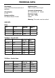
Technical data

INSTALLATION - 90CM
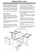
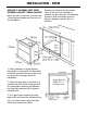
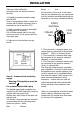
Dimensions
The appliance is designed to t into a
standard 600mm wide housing unit, with
minimum internal dimensions as shown.
Note: All sizes are nominal, some variation
is to be expected.
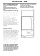
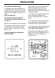
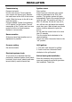
Step 2 : Connect to gas supply
1. The inlet to the appliance is ISO 7
- Rp ½” internal thread situated
towards the top right hand rear corner.
2. Fit the bayonet connection to the wall
in shaded area as shown.
The shaded area shown is applicable to
installations in minimum depth cabinets.
If more room is available, the bayonet
xing area can be extended, provided that
the exible tube does not obscure the fan
intake.
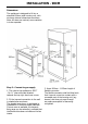
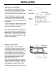
3. Use a 900mm - 1125mm length of
exible connector.
The exible connector shall be tted such
that it cannot come into contact with a
moveable part of the housing unit (eg;
drawer) and does not pass through
any space susceptible of becoming
congested.