
Install Instructions


26
IX. Service and Maintenance
A. General. Inspection and service should be conducted
annually. Turn off electrical power and gas supply
while conducting service or maintenance. Follow
instructions TO TURN OFF GAS TO APPLIANCE.
See Figure 16.
CAUTION
Label all wires prior to disconnection when
servicing controls. Wiring errors can cause
improper and dangerous operation. Verify proper
operation after servicing.
B. Low Water Cutoff (if so equipped). Follow
instructions provided with low water cutoff.
C. Inspect Vent System. See Figure 22.
1. Remove obstructions in vent pipe and chimney.
2. Remove soot accumulations with wire brush and
vacuum.
3. Repair or replace deteriorated vent pipe and vent
accessories.
4. Provide proper support. Repair sags, particularly in
horizontal sections.
5. Repair leaking joints.
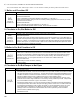
D. Inspect Boiler Flue Passages for blockage or soot
accumulation. See Figure 22.
1. Remove vent pipe, vent damper, blocked vent
switch and draft hood.
2. Remove sheet metal screws securing Jacket Top
Panel. Lift panel and rotate about safety relief valve
piping until top of boiler is exposed. If piping or
wall prevent full rotation of top panel for access to
canopy, cut slot into safety relief valve opening and
remove top panel.
3. Remove carriage bolts securing Canopy to Section
Assembly. For high efciency models (CG-DH)
remove ue bafes.
4. Using ashlight, examine all ue passageways.
a. If passageways are free of soot and obstruction,
replace canopy, secure and seal.
b. If passageways need cleaning, remove burners
as described in Paragraph E. Using long handle
wire or bristle ue brush and vacuum, brush
ueways thoroughly from top of boiler as
illustrated in Figure 22. Replace canopy and
seal.
5. Install ue bafes (if used).
6. Install new gasket material (See Section IX: Repair
Parts). Install canopy. Secure with carriage bolts.
7. Install Jacket Top Panel, Draft Hood, Blocked Vent
Switch, Vent Damper, and vent pipe.
E. Clean Main Burners and Firebox.
1. To remove burners for cleaning, changing orices,
or repairs:
a. Remove Jacket Front Panel.
b. Disconnect pilot tubing at gas valve.
c. Disconnect 3-wire plug at the gas valve.
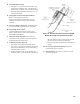
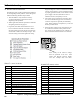
d. 40mm burners only. Remove injection shield
assembly, where used. See Figure 26.
e. Remove wires to ame roll-out switch.
f. Remove the burner access panel.
g. Mark the location of the pilot main burner on the
manifold if the marking on manifold is missing
or obliterated.
h. Hold burner at throat. Lift front of burner to
clear orice. Burner which holds pilot can only
be removed by lifting the burner adjacent to its
right rst.
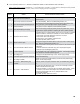
Table 9: Pilot Burner Location
Boiler
Model
Main Burner with
Pilot Bracket *
Pilot Burner
Located Between
Main Burners *
1 Inch 40mm 1 Inch 40mm
CG20 1 1 1 & 2 ---
CG30 1 1 1 & 2 1 & 2
CG40 2 2 2 & 3 2 & 3
CG50 3 2 3 & 4 2 & 3
CG60 4 3 4 & 5 3 & 4
CG70 6 3 6 & 7 3 & 4
CG80 7 4 7 & 8 4 & 5
CG90 8 4 8 & 9 4 & 5
CG100 9 5 9 & 10 5 & 6
* Main burners are numbered left to right as viewed from
front of boiler.
WARNING
Service on this boiler should be undertaken only by trained and skilled personnel from a qualied
service agency. Inspections should be performed at intervals specied in this manual. Maintain
manual in a legible condition.
Keep boiler area clear and free of combustible materials, gasoline and other ammable vapors and
liquids.
Do not place any obstructions in boiler room that will hinder ow of combustion and ventilation air.