Installation, Operating and Service Instructions for AP-U TM • Natural Draft • Oil-Fired • Water Boiler Models: • AP-110U-N • AP-110U-T • AP-154U-N • AP-154U-T Manual Contents 1. 2. 3. 4. 5. 6. 7. 8. 9. 10. 11. 12. Page General Information. . . . . . . . . . . . . . . . . . . . . . 5 Pre-Installation. . . . . . . . . . . . . . . . . . . . . . . . . . 7 Water Piping and Trim. . . . . . . . . . . . . . . . . . . 10 Venting . . . . . . . . . . . . . . . . . . . . . . . . . . . . . . . 15 Electrical. . .
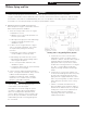
AP-U Installation & Service Manual IMPORTANT INFORMATION - READ CAREFULLY All boilers must be installed in accordance with National, State and Local Plumbing, Heating and Electrical Codes and the regulations of the serving utilities. These Codes and Regulations may differ from this instruction manual. Authorities having jurisdiction should be consulted before installations are made. In all cases, reference should be made to the following Standards: USA BOILERS A.
AP-U ! Installation & Service Manual DANGER DO NOT store or use gasoline or other flammable vapors or liquids in the vicinity of this or any other appliance. ! WARNING Improper installation, adjustment, alteration, service or maintenance can cause property damage, personal injury or loss of life. Failure to follow all instructions in the proper order can cause personal injury or death.
AP-U ! Installation & Service Manual WARNING This boiler contains very hot water under 12 - 15 PSI pressure. DO NOT unscrew any pipe fittings nor attempt to disconnect any components of this boiler without positively assuring the water is cool and has no pressure. Always wear protective clothing and equipment when installing, starting up or servicing this boiler to prevent scald injuries. DO NOT rely on the pressure and temperature gauges to determine the temperature and pressure of the boiler.
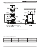
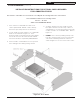
AP-U Installation & Service Manual 1 General Information Figure 1-1: AP-U Series Boiler Dimensional Data Table 1-2: Dimensional D (See Figure 1-1) Boiler Model Number Dimension ‘A’ Water Capacity (gallons) Approx. Shipping Weight (lb.) AP-110U-N(T) 34-9/16 10.1 300 AP-154U-N(T) 41” 15.4 355 Note: Maximum Working Pressure: Water 30 PSI shipped standard.
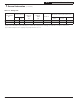
AP-U Installation & Service Manual 1 General Information (continued) Table 1-3: Rating Data Boiler Model No. Burner Capacity DOE Heating Capacity MBH MBH GPH (2) (1) AHRI NET Ratings - MBH (3) AFUE % Minimum Chimney Requirements AP-110U-N(T) 0.75 110 95 83 86.2 Round In. Dia. 6 AP-154U-N(T) 1.10 154 139 117 86.0 6 Rectangle Height Ft. In. x In.
AP-U Installation & Service Manual 2 Pre-Installation A. INSPECT SHIPMENT carefully for any signs of damage. 1. All equipment is carefully manufactured, inspected and packed. Our responsibility ceases upon delivery of crated boiler to the carrier in good condition. 2. Any claims for damage or shortage in shipment must be filed immediately against the carrier by the consignee.
AP-U Installation & Service Manual 2 Pre-Installation (continued) C. REMOVE CRATE 1. Remove all fasteners at crate skid. 2. Lift outside container and remove all other inside protective spacers and bracing. Remove accessory parts carton. D. REMOVE BOILER FROM SKID 1. Remove four (4) hex head lag screws, attaching boiler base plate to shipping skid. 2. Carefully, walk boiler to the edge of the skid. Tilt the boiler back, allowing boiler base edge to rest on the floor, then, remove the skid. 3.
AP-U Installation & Service Manual 2 Pre-Installation (continued) INSTALLATION INSTRUCTIONS FOR OPTIONAL SHIELD REQUIRED FOR COMBUSTIBLE FLOOR This shield for combustible floors is intended for use only with the following New Yorker oil-fired boilers: Use Part Number 6183504 for the following models: AP-110U AP-154U ADDS 4-3/16” TO BOILER HEIGHT 1. Place shield on combustible floor with “TOP” surface upward and “FRONT” surface directly below the expected position of the oil burner. 2.
AP-U Installation & Service Manual 3 Water Piping and Trim ! WARNING Failure to properly pipe boiler may result in improper operation and damage to boiler or structure. Oxygen contamination of boiler water will cause corrosion of iron and steel boiler components, and can lead to boiler failure. New Yorker’s Standard Warranty does not cover problems caused by oxygen contamination of boiler water or scale (lime) build-up caused by frequent addition of water. A.
AP-U Installation & Service Manual 3 Water Piping and Trim (continued) d. Use a system bypass if the boiler is to be operated in a system which has a large volume or excessive radiation where low boiler water temperatures may be encountered (i.e. converted gravity circulation system, etc.
Figure 3-3: Recommended Boiler Piping for Circulator Zoned Heating Systems, Supply Side Circulator AP-U 12 Installation & Service Manual 3 Water Piping and Trim (continued) 110839-01 - 8/20
Figure 3-4: Boiler Piping for Zone Valve Zoned Heating Systems, Supply Side Circulator AP-U 110839-01 -8/20 Installation & Service Manual 3 Water Piping and Trim (continued) 13
AP-U Installation & Service Manual 3 Water Piping and Trim (continued) THE FOLLOWING GUIDELINES SHOULD BE FOLLOWED WHEN PIPING THE TANKLESS HEATER: dishwashers and automatic washers is possible by piping the hot water from the heater prior to entering the mixing valve. The mixing valve should be “trapped” by installing it below the cold water inlet to heater to prevent lime formation in the valve. Refer to Figure 3-5. 1.
AP-U Installation & Service Manual 4 Venting A. GENERAL GUIDELINES. 1. Vent system installation must be in accordance with these instructions and applicable provisions of local building codes. Contact local building or fire officials about restrictions and installation inspection in your area. 2. The AP-U Series is designed to be vented into a fireclay tile-lined masonry chimney or chimney constructed from type-L vent or a factory built chimney that complies with the type HT requirements of UL103.
AP-U Installation & Service Manual 4 Venting (continued) Figure 4-1: Recommended Smokepipe Arrangement and Chimney Requirements Figure 4-2: Draft Regulator Locations 16 110839-01 - 8/20
AP-U Installation & Service Manual 5 Electrical ! DANGER Positively assure all electrical connections are unpowered before attempting installation or service of electrical components or connections of the boiler or building. Lock out all electrical boxes with padlock once power is turned off. ! WARNING • Failure to properly wire electrical connections to the boiler may result in serious physical harm. • Electrical power may be from more than one source.
AP-U Installation & Service Manual Figure 5-1: Schematic Wiring Diagram 5 Electrical (continued) 18 110839-01 - 8/20
AP-U Installation & Service Manual 5 Electrical (continued) Figure 5-2: Schematic Wiring Diagram 110839-01 -8/20 19
AP-U Installation & Service Manual 6 Oil Piping A. GENERAL. B. SINGLE-PIPE OIL LINES. 1. Use flexible oil line(s) so that burner can be removed without disconnecting the oil supply. 2. A supply line fuel oil filter is recommended as a minimum for all firing rates but a pleated paper fuel oil filter is recommended for the lowest firing rate application to prevent nozzle fouling. 3. Use Flared fittings only. DO NOT use compression fittings. 4.
AP-U Installation & Service Manual 6 Oil Piping (continued) Table 6-2: Single Stage Units (3450 RPM) Two Pipe Systems Lift "H" (See Figure) Maximum Length of Tubing "H" + "R" (See Figure) 3/8" OD Tubing (3 GPH) 1/2" OD Tubing (3 GPH) 0' 84' 100' 1' 78' 2' 73' 3' 4' Table 6-3: Two-Stage Units (3450 RPM) Two Pipe Systems Lift "H" (See Figure) Maximum Length of Tubing "H" + "R" (See Figure) 3/8" OD Tubing (3 GPH) 1/2" OD Tubing (3 GPH) 0' 93' 100' 100' 2' 85' 100' 100' 4' 77' 100' 68
AP-U Installation & Service Manual 7 System Start-Up A. ALWAYS INSPECT INSTALLATION BEFORE STARTING BURNER. 1. Verify that the venting, water piping, oil piping, and electrical system are installed properly. Refer to Installation Instructions contained in this manual. 2. Confirm all electrical, water and oil supplies are turned off at the source and that the vent is clear from obstructions. ! WARNING Completely read, understand and follow all instructions in this manual before attempting start up. B.
Installation & Service Manual AP-U 7 System Start-Up (continued) 4. WATER BOILERS WITH TANKLESS HEATERS: The Warm Start Boiler Control is factory programmed with a High Limit setpoint of 190°F. The High Limit setpoint is adjustable between 100°F and 220oF. Additionally, the Warm Start Boiler Control is factory programmed with a Low Limit setpoint off The Low Limit setpoint is adjustable between 110°F and 200°F. These temperatures may be varied to suit the installation requirements. 2.
AP-U Installation & Service Manual 7 System Start-Up (continued) G. START OIL BURNER. 1. Open vent fitting on fuel pump. 2. TURN ‘ON’ BURNER service switch and allow burner to run until oil flows from vent fitting in a SOLID stream without air bubbles for approximately 10 seconds. 3. Close vent fitting and burner flame should start immediately after prepurge is completed. Prepurge prevents burner flame until 10 seconds has elapsed after initial power is applied to burner.
AP-U Installation & Service Manual 7 System Start-Up (continued) mounted on the bottom of the electronic ignitor. See Figure 7-4. To service cad cell or to replace the plug in portion, swing open the ignitor. After service is complete, be sure to fasten down the ignitor. I. CHECK FOR CLEAN CUT OFF OF BURNER. 1.
Installation & Service Manual AP-U 7 System Start-Up (continued) iii. Limited Recycle: This feature limits the number of recycle trials (for each call for heat) to a maximum of three trials. If the flame is lost three times and does not successfully satisfy a call for heat, the 7505 locks out. iv. Limited Reset (Restricted Mode): In order to limit the accumulation of unburned oil in the combustion area, the control can only be reset three times.
AP-U Installation & Service Manual 7 System Start-Up (continued) • Failure occurs, device enters Recycle Mode. • Device tries to restart system after approximately 60 seconds. • After third Recycle Mode trial, safety switch locks out within safety switch timing indicated on label and control enters Restricted Mode. Ignition and motor stop and oil valves closes. d. Power Failure Check: After Flame is established, turn the power off to the control/burner. The burner should shut down safely.
AP-U Installation & Service Manual 8 Operating A. Setting the High Limit: The high limit is factory set at 190oF. To adjust, turn the HI TEMP Dial A until the desired setting is displayed. (Setting range: 100o-220oF). efficiency. When activated, the control will supply latent heat that may remain in the boiler from a previous run cycle to the heating zone that is now calling.
AP-U Installation & Service Manual 8 Operating (continued) WARNING: DO NOT ADD WATER UNTIL THE BOILER HAS FULLY COOLED. To activate Manual Reset LWCO mode 1. Turn the LO TEMP dial to access the Program Mode - indicated in the display as Pro 2. Turn the HI TEMP dial to select feature 3 3. Push the Test/Setting Button to A for Automatic Reset Mode 4. Reset LO TEMP and HI TEMP settings to desired temperatures.
AP-U Installation & Service Manual 8 Operating (continued) Dial Setting Feature Options Description Default Setting 1 Thermal Pre-Pruge OFF ON Purge Inactive Purge Active OFF 2 Fahrenheit or Celsius F C Degrees Fahrenheit Degree Celcius F 3 LWCO Manual or Automatic Reset A b Automatic Reset Manual Reset A 4 Circulator Options A b c Circulator operation on TT call only Circulator operation on ZC/ZR call only Circulator operation on call from either A 5 Circulator Hold Off ON OFF
AP-U Installation & Service Manual 8 Operating (continued) ! WARNING Allow the boiler to fully cool before adding water. e. ECONOMY ACTIVE Indicates that the Thermal Targeting function is active and the Fuel Smart HydroStat will reduce boiler temperature to conserve fuel. The Economy feature is activated using the ECONOMY dial. (See “How Thermal Targeting Works” for more information). f.
AP-U Installation & Service Manual 9 Maintenance & Service Instructions A. WATER BOILERS: 1. Filling of boiler and system. GENERAL — In a hot water heating system, the boiler and entire system (other than the expansion tank) must be full of water for satisfactory operation. Water should be added to the system until the boiler pressure gauge registers 12 psi. To insure that the system is full, water should come out of all air vents when opened. 2. BOILING OUT OF BOILER AND SYSTEM.
AP-U Installation & Service Manual 9 Maintenance & Service Instructions (continued) 3. With steam boilers, at end of season add sufficient water to fill boiler to top of water column and leave it that way until fall when water should be drained again to proper level. If, at this time, boiler water is dirty, drain water, flush out boiler, and refill with clean water to prescribed water level. 4. Always keep the manual fuel supply valve shut off if the burner is shut down for an extended period of time.
AP-U Installation & Service Manual 10 Boiler Cleaning NOTICE: BURNER SHUTDOWN: Open Service Switch to turn off burner. Manual Oil Supply Valve should be closed and Electric Service to boiler turned off if boiler will not be operated for an extended period of time. A. GENERAL. Inspection service and cleaning should be conducted annually. Turn off electric power and close oil supply valve while conducting service or maintenance. B. FIRETUBES AND COMBUSTION CHAMBER. (See Figure 10-1) 1.
AP-U Installation & Service Manual 10 Boiler Cleaning (continued) Important Product Safety Information: Refractory Ceramic Fiber Product WARNING Some boiler components contain refractory ceramic fibers (RCF). RCF has been classified as a possible human carcinogen. When exposed to temperatures above 1805°F, such as during direct flame contact, RCF changes into crystalline silica, a known carcinogen.
AP-U Installation & Service Manual 11 Troubleshooting A. COMBUSTION 1. NOZZLES — Although the nozzle is a relatively inexpensive device, its function is critical to the successful operation of the oil burner. The selection of the nozzle supplied with the AP-U boiler is the result of extensive testing to obtain the best flame shape and efficient combustion. Other brands of the same spray angle and spray pattern may be used but may not perform at the expected level of CO2 and smoke.
AP-U Installation & Service Manual 11 Troubleshooting (continued) NOTICE: CHECK TEST PROCEDURE. A very good test for isolating fuel side problems is to disconnect the fuel system and with a 24” length of tubing, fire out of an auxiliary five gallon pail of clean, fresh, warm #2 oil from another source. If the burner runs successfully when drawing out of the auxiliary pail then the problem is isolated to the fuel or fuel lines being used on the jobsite. e.
AP-U Installation & Service Manual 11 Troubleshooting (continued) Burner Will Not Fire See Flow Chart 1 Burner Will Not Shut Down See Flow Chart 2 Temperature Display Exceeds High Limit Setting Under normal operation, boiler temperature will continue to rise after the control shuts off the burner. This condition, known as “thermal stacking”, results from hot boiler surfaces continuing to release heat into the boiler water.
Installation & Service Manual AP-U Troubleshooting 11 Troubleshooting (continued) Flow Chart 1 – Burner Will Not Fire Troubleshooting Flow Chart 1 - Burner Will Not Fire Does the Display Read YES The Control is Purging Latent Heat from the Boiler. NO The Control is Not Powered. ? The Thermal Pre-Purge feature holds off the burner until the control determines if the latent heat in the boiler can satisfy the heat call.
AP-U Installation & Service Manual 11 Troubleshooting (continued) Troubleshooting Flow Chart2 1–- Burner Burner Will Shut Down Troubleshooting Flow Chart WillNot Not Shut Down Is the Red LED (LOW WATER) On? YES The Control is Sensing Low Water. Is either Yellow LED On? WARNING! TURN OFF POWER TO BURNER IMMEDIATELY! NO CAUTION – ALWAYS ALLOW A BOILER TO FULLY COOL BEFORE ADDING WATER. YES The Control has Reached Target or High Limit Temperature. YES The Control is Operating Normally.
AP-U Installation & Service Manual This page intentionally left blank.
AP-U Installation & Service Manual 12 Service Parts All AP-U™ Series Service Parts may be obtained through your local New Yorker Wholesale distributor. Should you require assistance in locating a New Yorker distributor in your area, or have questions regarding the availability of New Yorker products or service parts, please contact: New Yorker Boiler Co., Inc., P.O. Box 3005, Lancaster, PA 17604-3005, ATTN: Customer Service Department.
AP-U Installation & Service Manual 12 Service Parts (continued) AP-U Bare Boiler Item No.
AP-U Installation & Service Manual 12 Service Parts (continued) Figure 12-2: Service Parts Jacket and Trim NOTE: When ordering parts always give the serial number and model number shown on the boiler.
Installation & Service Manual AP-U 12 Service Parts (continued) AP-U Trim Item No.
AP-U Installation & Service Manual SERVICE RECORD DATE 46 SERVICE PERFORMED 110839-01 - 8/20
AP-U Installation & Service Manual SERVICE RECORD DATE 110839-01 -8/20 SERVICE PERFORMED 47
AP-U 48 Installation & Service Manual 110839-01 - 8/20