
Install Instructions


2
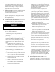
Table 1: Dimensional Data
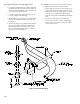
Figure 1: Dimensional Drawing
The following terms are used throughout this manual to bring attention to the presence of hazards of various
risk levels, or to important information concerning product life.
DANGER
Indicates an imminently hazardous situation
which, if not avoided, will result in death, serious
injury or substantial property damage.
CAUTION
Indicates a potentially hazardous situation which,
if not avoided, may result in moderate or minor
injury or property damage.
WARNING
Indicates a potentially hazardous situation which,
if not avoided, could result in death, serious injury
or substantial property damage.
NOTICE
Indicates special instructions on installation,
operation, or maintenance which are important
but not related to personal injury hazards.
Boiler
Size
Dimensions [Inches]
Recommended
Vent Size
[2]
Gas
Connection
[FPT]
Water
Content
[gallons]
Approx.
Shipping
Weight
[lb.]
'A' 'B' 'C' 'D' 'E' 'F' 'G'
20 20-1/4 10-3/4 6-3/8 4 45-5/8 8-1/2 10 [1] 4" Dia. 1/2 2.5 212
30 21-1/2 12 6 4 45-3/4 8-1/2 4-3/4 4" Dia. 1/2 3.2 254
40 24-3/4 15-1/4 7-5/8 5 47-1/8 9-1/8 4-3/4 5" Dia. 1/2 4.0 298
50 28 18-1/2 9-1/4 6 48-1/2 9-3/4 5-1/4 6" Dia. 1/2 4.7 346
60 31-1/4 21-3/4 10-7/8 6 48-1/2 9-3/4 5-1/4 6" Dia. 1/2 5.5 408
70 34-1/2 25 12-1/2 7 50-1/8 10-3/8 6-5/8 7" Dia. 3/4 6.2 450
80 37-3/4 28-1/4 14-1/8 7 50-1/8 10-3/8 6-5/8 7" Dia. 3/4 7.0 506
90 41 31-1/2 15-3/4 8 52 11 7-1/4 8" Dia. 3/4 7.7 550
100 44-1/4 34-3/4 17-3/8 8 52 11 7-1/4 8" Dia. 3/4 8.5 608
[1] CG20D only. Dimension 'G' includes allowance for 4" x 3" reducer furnished with boiler. See Figure 10.
[2] Refer to the National Fuel Gas Code for equivalent areas of circular and rectangular ue linings.
Maximum Allowable Working Pressure, Water - 50 PSI
Safety Relief Valve Pressure, Water - 30 PSI shipped from factory (std.)