
Install Instructions


8
Adjust valves to provide 180° to 200°F supply water
temperature. Opening the boiler supply valve will raise
system temperature, while opening by-pass valve will
lower system supply temperature.
I. If it is required to perform a long term pressure
test of the hydronic system, the boiler should rst be
isolated to avoid a pressure loss due to the escape of air
trapped in the boiler.
To perform a long term pressure test including the
boiler, ALL trapped air must rst be removed from the
boiler.
A loss of pressure during such a test, with no visible
water leakage, is an indication that the boiler contained
trapped air.
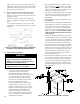
Figure 5: Recommended Piping for Combination
Heating & Cooling (Refrigeration) Systems
J. Optional LWCO Installation
WARNING
DO NOT ATTEMPT to cut factory wires to
install an aftermarket Low Water Cut Off
(LWCO). Only use connections specically
identied for Low Water Cut Off.
In all cases, follow the Low Water Cut Off
(LWCO) manufacturer’s instructions.
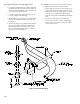
Figure 6: Recommended Probe LWCO Location
1. A low water cutoff is required to protect
a gas-red hot water boiler when any
connected heat distributor (radiation) is
installed below the top of the hot water boiler
(i.e. baseboard on the same oor level as
the boiler). In addition, some jurisdictions
require the use of a LWCO with a hot water
boiler as a redundant safety control.
It is recommended that the LWCO control
is installed above the boiler to provide the
highest level of protection. However, where
the LWCO control is approved by the LWCO
control manufacturer for installation in a
high boiler tapping of a water boiler, the
use of the listed LWCO control is permitted
when it is installed according to the LWCO
manufacturer's instructions.
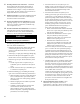
2. The recommended location for a LWCO on gas
hot water boilers is above the boiler, in the supply
piping. The minimum safe water level of a water
boiler is at the uppermost top of the boiler; that is, it
must be full of water to operate safely.
3. Typically, in residential applications, a probe type
LWCO is used instead of a oat type, due to their
relative costs and the simplicity of piping for a
probe LWCO.
4. Piping and ttings required to install LWCO are
eld supplied.
5. When constructing a piping tree to install LWCO
select ttings (tees, elbows etc) and nipples to have
the same size (NPT) as boiler supply connection.
At minimum, 1-1/4” tee with ¾” branch outlet is
required to connect the probe LWCO to the supply
piping. See Figure 6. DO NOT REDUCE THE
SIZE OF NEAR BOILER SUPPLY FITTINGS
AND NIPPLES.
6. Installation of manual shutoff valve located above
the LWCO and the boiler is recommended to allow
servicing. Thus LWCO probe can be removed for
inspection without draining the heating system. An
annual inspection of the probe is recommended.
7. The presence of water covering properly installed
LWCO probe will cause the normally open contact
of the LWCO to close, thus providing continuity of
the 24 VAC service to the boiler gas valve. When
water level drops below probe, LWCO contact
opens up breaking 24V supply to gas valve and
preventing the boiler to re.
8. 2012 compliant CG-D Series gas hot water boilers
have a “plug-in” provision in factory wiring that
will accept optional 24VAC probe LWCO harness
connector. The optional LWCO kit (P/N 104083-
01) includes 24VAC probe LWCO, Harness and
Instructions addressing piping, wiring and testing
after installation.