INSTALLATION, OPERATING AND SERVICE INSTRUCTIONS CG-D™ Series GAS BOILER 9700609 BEFORE INSTALLATION: READ THIS MANUAL SAVE THESE INSTRUCTIONS Installing contractor and homeowner should read and be informed as to the proper installation and operation of this boiler. The manufacturer will not be responsible for improper installation or operation. This manual and all associated instruction material should be conspicuously posted near the boiler.
The following terms are used throughout this manual to bring attention to the presence of hazards of various risk levels, or to important information concerning product life. DANGER CAUTION Indicates an imminently hazardous situation which, if not avoided, will result in death, serious injury or substantial property damage. Indicates a potentially hazardous situation which, if not avoided, may result in moderate or minor injury or property damage.
The City of New York requires a Licensed Master Plumber supervise the installation of this product. The Massachusetts Board of Plumbers and Gas Fitters has approved the CG-D™ Series Boiler. See the Massachusetts Board of Plumbers and Gas Fitters website, http://license.reg.state.ma.us/pubLic/pl_products/pb_pre_form.asp for the latest Approval Code or ask your local Sales Representative. The Commonwealth of Massachusetts requires this product to be installed by a licensed Plumber or Gas fitter.
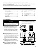
E. Provide practical service clearances. A minimum of 24" from the left side and front jacket panels is recommended for servicing but may be reduced to minimums shown in Figure 2. Subject to boiler and system piping, left side clearance may be reduced to 1" if right side clearance is increased to 9". F. Install on level floor. For basement installation provide concrete base if floor is not level or if water may be encountered on floor around boiler. G.
II. Unpack Boiler CAUTION Do not drop boiler. Do not bump boiler jacket against floor. A. Move boiler to approximate installed position. B. Remove all crate fasteners. C. Lift outside container and remove with all other inside protective spacers and bracing. Save two of the wooden slats from the container sleeve for use in Steps E and F. D. Remove all boiler hold-down fasteners. E. Tilt the boiler to one side and slide a wooden slat under the two raised feet. F.
Figure 3: Recommended Water Piping for Zone Valve Zoned Heating Systems
Figure 4: Recommended Water Piping for Circulator Zoned Heating Systems
Adjust valves to provide 180° to 200°F supply water temperature. Opening the boiler supply valve will raise system temperature, while opening by-pass valve will lower system supply temperature. I. If it is required to perform a long term pressure test of the hydronic system, the boiler should first be isolated to avoid a pressure loss due to the escape of air trapped in the boiler. To perform a long term pressure test including the boiler, ALL trapped air must first be removed from the boiler.
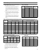
IV. Gas Piping A. Size gas piping. Design system to provide adequate gas Table 2: Rated Input supply to boiler. Consider these factors: 1. Allowable pressure drop from point of delivery to boiler. Maximum allowable system pressure is ½ psig. Actual point of delivery pressure may be less; contact gas supplier for additional information. Minimum gas valve inlet pressure is listed on rating label. 2. Maximum gas demand. Table 2 lists boiler input rate.
B. Connect boiler gas valve to gas supply system. 1. Use methods and materials in accordance with local plumbing codes and requirements of gas supplier. In absence of such requirements, follow National Fuel Gas Code, NFPA 54/ANSI Z223.1. 2. Use thread (joint) compounds (pipe dope) resistant to action of liquefied petroleum gas. 3. Install sediment trap, ground-joint union and manual shut-off valve upstream of boiler gas control valve. See Figure 7. 4.
V. Venting A. Install vent system in accordance with local building codes; or local authority having jurisdiction; or National Fuel Gas Code, ANSI Z223.1/NFPA 54. Install any of the following for this CG-D Series Category I, draft hood equipped appliance: 1. Type B or Type L gas vent. Install in accordance with listing and manufacturer's instructions. 2. Masonry or metal chimney.
CAUTION DANGER Do not use one vent damper to control two heating appliances. Inspect existing chimney before installing boiler. Failure to clean or replace perforated pipe or tile lining will cause severe injury or death. 1. The vent damper must be the same size as the outlet of the Draft Hood supplied with the boiler (see Figure 1). Unpack the damper carefully - DO NOT FORCE IT CLOSED! Forcing the damper may damage the gear train and void the warranty. 2.
4. Do not connect into same leg of chimney serving an open fireplace. 5. Inspect chimney for obstructions or restrictions and remove. Clean chimney if necessary. 6. Vent pipe to chimney must not be smaller than outlet on draft hood or damper. Although single wall vent pipe may be used, Type B is recommended. The venting system must be arranged so that only the boiler is served by the damper device. Installation per paragraph (C) complies with this provision. 7.
VI. Electrical A. General. Install wiring and ground boiler in accordance with requirements of authority having jurisdiction, or in absence of such requirements the National Electrical Code, ANSI/NFPA 70. B. Install thermostat. Locate on inside wall approximately 4 feet above floor. Do not install on outside wall, near fireplace, or where influenced by drafts or restricted air flow, hot or cold water pipes, lighting fixtures, television, or sunlight.
Figure 11: Wiring Schematic, Boiler Control 15
Figure 12: Wiring Schematic, Boiler Control 16
Figure 13: Wiring Schematic, Zone Valves Figure 14: Wiring Schematic, Zone Circulators 17
VII. System Start-up and Checkout A. Main Burner Check - Check main burners to see that they were not dislodged during shipment. Rear of burners should be in the vertical slots in the rear of burner tray and the front of the burners should be seated completely on the orifices. B. Initial start 1. Fill entire heating system with water and vent air from system. Use the following procedure on a System equipped with zone valves. (See Figure 3). a. Close isolation valve in boiler supply piping. b.
Figure 16: Operating Instructions 19
C. Check Gas Input to Boiler NOTICE CG-D Series boilers built for installation at altitudes greater than 2,000 feet above sea level have been specially orificed to reduce gas input rate 4 percent per 1,000 feet above sea level per the National Fuel Gas Code, NFPA 54/ANSI Z223.1. High altitude boiler models are identifiable by the third digit in the model number suffix on the rating label: CG_OD- _ _ 2: less than 2000 ft. elevation CG_OD- _ _ 5: 2000 to 5000 ft. elevation 1.
E. Check Pilot Burner Flame. 1. See Figure 19. The pilot burner should be lit only if thermostat is calling for heat. The pilot burner produces three (3) flames. The center flame should be steady, medium hard blue enveloping 3/8 to 1/2 inch of thermocouple. F. Check Ignition System Safety Shut-off Device. Remove 3-wire plug from gas valve. If burners do not shut down determine cause of malfunction. Replace necessary items and check operation. G. Check Vent Damper Operation.
VIII. Operation A. BOILER SEQUENCE OF OPERATION NORMAL OPERATION 1. The CG-D Series Boilers are equipped with a Boiler Control (control). This control replaces the traditional separate ignition control, high limit switch and circulator relay and adds energy saving thermal purge features. Energy is saved by starting the circulator and delaying the burner start when there is residual heat available in the boiler. 2. The boiler’s sequence of operation is shown in Table 4. 3.
For example, when the “I” key is pressed on the control until “bt” is displayed, it will then flash a three digit number (such as “180”) followed by either “F” (or “C”). This indicates that the boiler water temperature is 180°F. Other operating parameters display the information in a similar fashion. 1 sec Figure 21: Boiler Display The control display, along with Up ñ, Down ò, and “I” keys may be used to view boiler operating status (Figure 21). D.
2. Differential (df_) The control is factory programmed with a Differential of 15°F. The Differential is the number of degrees the boiler temperature must decrease below the Operating Setpoint before the boiler can restart. The differential is adjustable between 10° through 30°F. 3. Circulator Overrun Time (OR_) The control is factory programmed with a Circulator Overrun Time of 0 minutes.
Table 7: DHW Terminal Function () Selection = Domestic Hot Water Demand, (Parameter dh_ = dh) Call for Heat Circulator Status T-T Input DHW Input Priority Time (Pt_) System DHW Circulator Circulator Output Output on off On on off on on On off off on On on off OFF Table 8: DHW Terminal Function () Selection = Second Heating Zone, (Parameter dh_ = tt2) Call for Heat Circulator Status T-T Input DHW Input System Circulator Output (Zone 1) DHW Circulator Output (Zone 2) on off
IX. Service and Maintenance WARNING Service on this boiler should be undertaken only by trained and skilled personnel from a qualified service agency. Inspections should be performed at intervals specified in this manual. Maintain manual in a legible condition. Keep boiler area clear and free of combustible materials, gasoline and other flammable vapors and liquids. Do not place any obstructions in boiler room that will hinder flow of combustion and ventilation air. A. General.
7. Connect pilot gas supply, igniter/sensor wire, and ground wire at Boiler Control. 8. Install Burner Access Panel. Connect Flame Rollout Switch wires. F. Check Operation. Follow steps C through J from Section VII: System Start-up. G. Removal or replacement of pilot assembly or pilot assembly parts. If pilot assembly, sensor or pilot orifice need replacing, remove main burner with pilot using procedure described in Paragraph E. 1. To replace orifice spud: a. Disconnect pilot tubing.
X. Troubleshooting A. Before troubleshooting diagram in Figures 13 and 14. Ensure that incoming 120 Vac power polarity is correct and that the boiler is properly grounded. Further, ensure that the control power supply is 24 VAC (minimum 18 VAC to maximum 30 VAC) and polarity is correct. The following pages contain trouble shooting tables for use in diagnosing control problems. When using these tables the following should be kept in mind: 1.
B. Use Control Display (error) Number To Direct TroubleShooting Efforts If the control detects an error it will flash “” (error) followed by a number. Use this number to identify the boiler problem and corrective action in the table below.
C. Use STA (status) Number To guide TroubleShooting The control will flash “” followed by a number. Use this number to identify the boiler problem in the table below: 1. Boiler and Circulator Off Display / Status Recommended Corrective Action The boiler has not detected a call for heat (tt = off and dh = off.
5. Circulator is On But Damper is Not Open Display / Status Recommended Corrective Action The control is waiting for the damper to open. Damper end switch has failed to close (end switch contact is stuck open). Combustion can never take place unless the damper blade is in the fully open position. Check the following: - During status “STA18" or “STA 20” the control terminal “P6 - 5” (yellow wire) is energized.
6. Circulator is On, Damper is Open But Boiler Fails to Start (continued) Display / Status Recommended Corrective Action 1. No Spark a. Can you hear sparking while is displayed? - If there is no spark noise replace the control. b.
XI. Repair Parts All CG-D™ Series repair parts may be ordered through New Yorker Boiler Co., Inc. or its authorized distributors. Should you require assistance in locating a New Yorker Distributor in your area, or have questions regarding the availability of New Yorker products or repair parts, please contact: New Yorker Boiler Co., Inc. P.O. Box 10 Hatfield, Pennsylvania 19440-0010 Phone: (215) 855-8055 Attn: Customer Service Department Section Assembly and Canopy Assembly......
Key No.
Section Assembly and Canopy Group 35
Key No.
Key No.
Key No.
Manifold and Main Burners (1 Inch Main Burners) 39
Key No.
Manifold and Main Burners (40mm Main Burners) 41
Key No. Description Part Number CG-D MODEL 20 30 40 50 60 70 80 90 100 Pilot Burner and Gas Valve, Natural & LP Gas 33 33A 103704-01 1 1 1 1 1 1 1 1 1 Pilot Burner, Honeywell Q3481B1420 (LP) 103705-01 1 1 1 1 1 1 1 1 1 Included with Pilot Burner 1 1 1 1 1 1 1 1 1 1 1 1 1 1 1 1 1 1 Included w/ Pilot Burner & Gas Valve 1 1 1 1 1 1 1 1 1 1 1 1 1 1 1 1 1 1 Gas Valve, Honeywell VR8204C3007 (Nat.
Key No.
Key No.
SERVICE RECORD DATE SERVICE PERFORMED 46
SERVICE RECORD DATE SERVICE PERFORMED 47