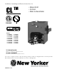
Installation, Operating and Service Instructions for CL TM • Natural Draft • Oil-Fired • Water & Steam Boiler 9700609 Models: • CL3-091W • CL3-105-W • CL3-140-W • CL4-126-W • CL4-175-W • CL4-210-W • CL5-168-W • CL5-245-W • CL5-230-W • CL3-091S • CL3-105S • CL3-140S • CL4-126S • CL4-175S • CL4-210S • CL5-168S • CL5-245S • CL5-280S TO THE INSTALLER: Affix these instructions adjacent to boiler. TO THE CONSUMER: Retain these instructions for future reference.
CL Installation & Service Manual IMPORTANT INFORMATION - READ CAREFULLY All boilers must be installed in accordance with National, State and Local Plumbing, Heating and Electrical Codes and the regulations of the serving utilities. These Codes and Regulations may differ from this instruction manual. Authorities having jurisdiction should be consulted before installations are made. In all cases, reference should be made to the following Standards: A. B. C. D.
CL Installation & Service Manual DANGER DO NOT store or use gasoline or other flammable vapors or liquids in the vicinity of this or any other appliance. WARNING Improper installation, adjustment, alteration, service or maintenance can cause property damage, personal injury or loss of life. Failure to follow all instructions in the proper order can cause personal injury or death.
CL Installation & Service Manual WARNING This boiler contains very hot water under high pressure. Do not unscrew any pipe fittings nor attempt to disconnect any components of this boiler without positively assuring the water is cool and has no pressure. Always wear protective clothing and equipment when installing, starting up or servicing this boiler to prevent scald injuries. Do not rely on the pressure and temperature gauges to determine the temperature and pressure of the boiler.
CL Installation & Service Manual 1 General Information 'B' 'C' DIA. NOTE: For Carlin Burners Only: Burner extends in front of boiler 11-1/4", burner swing door clearance is 10", burner extends 2-5/8" above floor and burner is not available with cover.
CL Installation & Service Manual 1 General Information (continued) 'A' 'B' 'C' DIA. NOTE: For Carlin Burners Only: Burner extends in front of boiler 11-1/4", burner swing door clearance is 10", burner extends 2-5/8" above floor and burner is not available with cover.
CL Installation & Service Manual 1 General Information (continued) Table 1: Dimensional Data / General Information (See Figures 1A Thru 1C) Dimensions Boiler Series Approx. Water Content Heat Transfer Surface Area - Sq. - Gallons Ft. "A" "B" "C" CL3 17-3/8" 8-1/4" 5-7/8" 16 14.33 CL4 22-3/8" 10-7/8" 6-7/8" 20 20.90 CL5 27-3/8" 13-3/8" 7-7/8" 24 27.
CL Installation & Service Manual 1 General Information (continued) Table 3A: Purpose of Tappings (Water) Tapping Location Size, NPT Purpose Less Heater With Heater A 1½” B ½” Return C ¼” D 1½” Supply E 1½” Optional Return Limit Well Plug Temperature/Pressure Gauge F ¾” G ¾” N/A Relief Valve H ¾” N/A Limit Well I ¾” N/A DHW Inlet DHW Outlet Figure 2A: Purpose of Tappings (Water) 8 103876-08 - 1/19
CL Installation & Service Manual 1 General Information (continued) Table 3B: Purpose of Tappings (Steam) Purpose Tapping Size, Location NPT Less Heater With Heater A B C D E F G H I J K L M N O P 1½” ½” ¼” 3” 1½” ¾” ¾” ¾” ¾” ¾” ¾” ½” ½” 1” ½” 1½” Return Pressure Limit Pressure Gauge Supply Optional Return Relief Valve N/A DHW Outlet N/A Limit Well N/A DHW Inlet Drain LWCO Water Gauge Glass Water Gauge Glass Indirect Water Heater Supply Indirect Water Heater Limit Surface Blowoff Figure 2B: Purpose of T
CL Installation & Service Manual 2 Pre-Installation (continued) A. INSPECT SHIPMENT carefully for any signs of damage. 1. All equipment is carefully manufactured, inspected and packed. Our responsibility ceases upon delivery of crated boiler to the carrier in good condition. 2. Any claims for damage or shortage in shipment must be filed immediately against the carrier by the consignee.
CL Installation & Service Manual 2 Pre-Installation (continued) WARNING Adequate combustion and ventilation air must be provided to assure proper combustion and to maintain safe ambient air temperatures. DO NOT install boiler where gasoline or other flammable vapors or liquids, or sources of hydrocarbons (i.e. bleaches, fabric softeners, etc.) are used or stored. 1. Determine volume of space (boiler room).
CL 3 Installation Instructions Installation & Service Manual 2. Place oil burner gasket on burner and align holes. A. REMOVE CRATE. 1. Remove all fasteners at crate skid. CAUTION 2. Lift outside container and remove all other inside protective spacers and bracing. Remove miscellaneous steam or water trim carton. Do not install burner without Gasket. 3. Remove four (4) 5/16-18 x 3/4” long cap screws from burner swing door used for mounting burner. B. REMOVAL OF BOILER FROM SKID. 1.
CL 3 Installation Instructions (continued) Instruction included with baffle. h. Reinstall Beckett MB(L1) or MD(V1) Head. i. Inspect and measure burner electrodes. Refer to Figure 27 for the proper electrode setting. Readjust electrode setting to the proper dimensions if necessary. Refer to Figure 27. j. Reinstall nozzle line electrode assembly. k. Connect copper connector tube. l.
CL 3 Installation Instructions (continued) Figure 8: Riello Turbulator Setting set to operate on a single line system. To operate on a two-line system the bypass plug must be installed. WARNING: DO NOT operate a single line system with the by-pass plug installed. Operating a single line system with the bypass plug installed will result in damage to the pump shaft seal. Note: Pump pressure was factory pre-set but must be checked at time of burner startup.
CL 3 Installation Instructions (continued) Figure 10: Electrode Settings m. Tighten knurled nut. n. Close igniter, rotate and tighten two (2) igniter latching screws. G. INSTALL WATER BOILER TRIM AND CONTROLS, (see Figures 1A and 1B). 1. Install return piping supplied with boiler. Apply Teflon or Sealant to all joints prior to assembly. Thread 1½" NPT x 5" Lg. return nipple into 1½" NPT tapping located in lower left corner of front section. Thread 1½" x ¾" x 1½" NPT tee onto 5" nipple.
Figure 12A: Recommended Water Piping for Circulator Zoned Heating System - Supply Side Circulator CL 16 Installation & Service Manual 3 Installation Instructions (continued) 103876-08 - 1/19
Figure 12B: Recommended Water Piping for Zone Valve Zoned Heating System - Supply Side Circulator CL 103876-08 - 1/19 Installation & Service Manual 3 Installation Instructions (continued) 17
CL Installation & Service Manual Figure 13: Recommended Boiler Piping for Gravity Return Steam Boiler 3 Installation Instructions (continued) 18 103876-08 - 1/19
CL Installation & Service Manual 3 Installation Instructions (continued) Note: • The GeniSys 7505 Oil Primary Control has pre-installed "T-T" jumper. To activate "T-T" terminals, "T-T" jumper must be removed. • DO NOT remove "T-T" jumper unless wiring diagram indicates a direct connection from thermostat and/or tankless heater aquastat control to the oil burner primary control's "TT" terminal. Refer to Figure 23. I. CONNECT SUPPLY AND RETURN PIPING TO HEATING SYSTEM. 1.
CL Installation & Service Manual 3 Installation Instructions (continued) b. Evaluate the Existing Steam System. The single most important factor in determining the expected life cycle of a steam boiler, is the amount of fresh water added to the boiler during operation. Fresh water brings minerals and oxygen into the boiler. These contaminants greatly accelerate corrosion of the cast iron boiler sections. i. Assure that all system radiators, piping and vents are absolutely leak tight.
CL 3 Installation Instructions (continued) away from the inlet so that the regulator is not subjected to excess temperatures that may occur during “off” periods when it is possible for heat to be conducted back through the supply line. The flow regulator also limits the flow of supply water regardless of inlet pressure variations in the range of 20 to 125 psi. 2.
CL Installation & Service Manual 3 Installation Instructions (continued) Figure 16: Indirect Water Heater Piping on CL Series Steam Boiler WARNING Vent this boiler according to these instructions. Failure to do so may cause products of combustion to enter the home resulting in severe property damage, personal injury or death. Insufficient Combustion Air Supply may result in the production and release of deadly carbon monoxide (CO) into the home which can cause severe personal injury or death.
CL Installation & Service Manual 3 Installation Instructions (continued) used. Only approved clay liners or listed chimney lining systems shall be used as specified in NFPA 31 or CSA B139. c. Abandoned Openings – Openings through the chimney wall that are no longer used shall be sealed in accordance to NFPA 211. Often abandoned openings are improperly sealed and usually covered by a gypsum wall covering. d. Clean Chimney – Chimney shall be free of all loose debris. 5.
CL 3 Installation Instructions (continued) the possibility that the flue gases could condense in the chimney connector or stack. term operation while in this condition may cause a venting failure and force flue gases into the living space. If the chimney is to be re-lined use the recommendations in NFPA 31, Appendix E or CSA B139. 2. NFPA 31 and CSA B139 have information to help the installer make an appropriate choice of venting materials.
CL Installation & Service Manual 3 Installation Instructions (continued) Two-Pipe Oil Lines - For two-pipe systems where more lift is required, the two-stage fuel unit is recommended. Table 5 (single-stage) and Table 6 (two-stage) show allowable lift and lengths of 3/8-inch and 1/2-inch OD tubing for both suction and return lines. Refer to Figure 20. Be sure that all oil line connections are absolutely airtight. Check all connections and joints. Flared fittings are recommended.
CL Installation & Service Manual 4 Electrical DANGER Positively assure all electrical connections are unpowered before attempting installation or service of electrical components or connections of the boiler or building. Lock out all electrical boxes with padlock once power is turned off. WARNING Failure to properly wire electrical connections to the boiler may result in serious physical harm. • Electrical power may be from more than one source.
Figure 21: Schematic Wiring Diagram, without Tankless Heater, Cold Start Control (All Burners) 4 Electrical (continued) 103876-08 - 1/19 REFER TO FIGURE 25 FOR SCHEMATIC WIRING DIAGRAM OF APPROPRIATE BURNER AND OIL PRIMARY CONTROL OPTION CL Installation & Service Manual 27
Figure 22: Schematic Wiring Diagram, with Tankless Heater, Warm Start Control (All Burners) 4 Electrical (continued) 28 REFER TO FIGURE 25 FOR SCHEMATIC WIRING DIAGRAM OF APPROPRIATE BURNER AND OIL PRIMARY CONTROL OPTION CL Installation & Service Manual 103876-08 - 1/19
103876-08 - 1/19 2 1-3 WH Jumper H-C Figure 23: Schematic Wiring Diagram, Steam Boilers With or Without Tankless Heater, McDonnell & Miller PSE-801 Probe LWCO, Beckett AFG and Carlin EZ Burners REFER TO FIGURE 25 FOR SCHEMATIC WIRING DIAGRAM OF APPROPRIATE BURNER AND OIL PRIMARY CONTROL OPTION N 1 BK B H 5 RD Lettered Terminals Numbered Terminals Wire Color McDonnell & Miller PSE-801 Terminals May Be Lettered or Numbered as Follows: CL Installation & Service Manual 4 Electrical (continued)
Figure 24: Schematic Wiring Diagram, Water Boilers with or without Tankless Heater, Hydrolevel HydroStat, All Burners REFER TO FIGURE 25 FOR SCHEMATIC WIRING DIAGRAM OF APPROPRIATE BURNER AND OIL PRIMARY CONTROL OPTION CL Installation & Service Manual 4 Electrical (continued) 103876-08 - 1/19
CL Installation & Service Manual 4 Electrical (continued) NOTE: APPLY THIS BURNER SCHEMATIC TO APPROPRIATE STEAM OR WATER BOILER CONTROL SCHEMATIC, REFER TO FIGURES 21 THRU 24 NOTE: APPLY THIS BURNER SCHEMATIC TO APPROPRIATE STEAM OR WATER BOILER CONTROL SCHEMATIC, REFER TO FIGURES 21, 22 AND 24 NOTE: APPLY THIS BURNER SCHEMATIC TO APPROPRIATE STEAM OR WATER BOILER CONTROL SCHEMATIC, REFER TO Figures 21 THRU 24 Figure 25: Schematic Wiring Diagrams For All Burner Options w/Various Oil Primary Controls 1
CL Installation & Service Manual 5 System Start-Up WARNING All boilers equipped with burner swing door have a potential hazard which can cause severe property damage, personal injury or loss of life if ignored. Before opening swing door, turn off service switch to boiler to prevent accidental firing of burner outside the combustion chamber. Be sure to tighten swing door fastener completely when service is completed. A. ALWAYS INSPECT INSTALLATION BEFORE STARTING BURNER. 1.
CL 5 System Start-Up (continued) Specifications Table 14A at the rear of this manual. c. Open all oil line valves. d. Attach a plastic hose to fuel pump vent fitting and provide a pan to catch the oil. e. Open Flame Observation Port cover on burner swing door. 2. Riello Burners a. Inspect Riello head setting on left side of burner by reading the scale embossed on the housing cover. Refer to Figure 8. 3.
CL 5 System Start-Up (continued) Installation & Service Manual Beckett MD(V1) (variable) Head burners have the ability to control air by moving the head. It might be necessary to move the head forward or back one position at a time to optimize the smoke and CO2 readings. See Figure 27 and Table 14A at the rear of this manual. 4. Riello Burners - Readjust the turbulator setting, only if necessary. a.
Figure 27: "L1" and "V1" Head Electrode Positioning and Gun Setting (Beckett AFG) CL 103876-08 - 1/19 Installation & Service Manual 5 System Start-Up (continued) 35
CL 5 System Start-Up (continued) 9. Flame Failure The CL boiler controls operate the burner automatically. If for unknown reasons the burner ceases to fire and the reset button on the primary control has tripped, the burner has experienced ignition failure. Refer to Oil Primary Control features, Paragraph I, Step 2 of this Section and Section IX, Troubleshooting, Paragraph B. If the failure re-occurs, call your heating contractor immediately before pressing the reset button.
CL Installation & Service Manual 5 System Start-Up (continued) • Release the reset button. The yellow light will turn off and the burner will start up again. • At burner start up, click the reset button while the igniter is till on. This will transition the control to a dedicated Pump Prime mode, during which the motor, igniter, and valve are powered for four (4) minutes. The yellow light will be on.
CL 5 System Start-Up (continued) b. Allow burner to run until boiler water temperature exceeds high limit setting. The burner should shut down and circulators continue running. c. Allow the temperature to drop below control setting. The burner must restart. d. Boiler installation is not considered complete until this check has been made. • If safety switch shuts down burner and resistance is above 1600 OHMS, open line switch to boiler.
CL Installation & Service Manual 6 Operating (continued) A. WATER BOILERS SEQUENCE OF OPERATION 1. Water Boilers Without Tankless Heaters (Cold Start), Sequence Of Operation: a. The CL Boiler is equipped with an Intelligent Oil Boiler Control (Cold Start Boiler Control). The boiler control replaces the traditional electronic aquastat and circulator relays and adds energy saving thermal purge features.
CL 6 Operating (continued) For example, when the “I” key is pressed on the Boiler Control until “bt” is displayed, it will then flash a three digit number (such as “180”) followed by either “F” (or “C”). This indicates that the boiler water temperature is 180°F. Other operating parameters display the information in a similar fashion. reset by pressing the reset button located on the primary control.
CL 6 Operating (continued) The Low Limit Differential is adjustable between 10°F and 25°F. c. Press the Up and Down keys to adjust the displayed setpoint to the desired value. e. Circulator Overrun Time (OR_) Circulator Overrun Time (also called “circulator off delay” or “circulator post purge”) continues circulator operation after a call for heat has ended, sending excess heat from the boiler into the priority zone.
CL 6 Operating (continued) g. Start Temperature () The amount of “Heat available” is calculated by taking the difference between measured boiler water temperature and the Start Temperature setting. Useful “Heat Available” is dependent on the type of heating emitter installed in the home. Heat emitters require a certain minimum temperature to operate effectively. Our default settings reflect cast iron radiators.
CL 6 Operating (continued) Table 11: External Low Limit, Parameter zc_= ell Table 10: Zone Request, Parameter zc_= zr Call for Heat ZR T-T Input Input off on on off off off on on Circulator Status C1 ZC Output Output off on on off Installation & Service Manual Call for Heat T-T ZR Input Input off off on on off on on off limit contact closes (boiler water is cold) the boiler is started and the "ZC" and "C1" output terminals are de-energized.
CL 7 Maintenance and Service Instructions A. MAINTENANCE OF LOW WATER CUT-OFF DEVICES WARNING Probe and float type low water cut-off devices require annual inspection and maintenance. 1. Although these devices are solid state in their operation, the probe is exposed to possible contamination in the boiler water and subject to fouling. 2. It is important to physically remove the probe from the boiler tapping annually and inspect that probe for accumulation of scale or sediment. 3.
CL Installation & Service Manual 7 Maintenance and Service Instructions (continued) iii. Start burner and operate sufficiently to boil the water without producing steam pressure. Boil for about 5 hours. Open boiler feed pipe sufficiently to permit a steady trickle of water from the surface blow-off pipe. Continue this slow boiling and trickle of overflow for several hours until the water coming from the overflow is clear. iv.
CL Installation & Service Manual 7 Maintenance and Service Instructions (continued) f. Boiler is now ready to be put into service. 2. Water Boilers: a. Filling of boiler and system. General — In a hot water heating system, the boiler and entire system (other than the expansion tank) must be full of water for satisfactory operation. Water should be added to the system until the boiler pressure gauge registers 12 psi. To insure that the system is full, water should come out of all air vents when opened. b.
CL Installation & Service Manual 7 Maintenance and Service Instructions (continued) 3. With steam boilers, at end of season add sufficient water to fill boiler to top of water column and leave it that way until fall when water should be drained again to proper level. If, at this time, boiler water is dirty, drain water, flush out boiler, and refill with clean water to prescribed water level. 4. Always keep the manual fuel supply valve shut off if the burner is shut down for an extended period of time.
8 Boiler Cleaning (continued) CL Installation & Service Manual Figure 32: Cleaning of Boiler Flueways 48 103876-08 - 1/19
CL Installation & Service Manual 8 Boiler Cleaning (continued) Important Product Safety Information Refractory Ceramic Fiber Product WARNING The Repair Parts list designates parts that contain refractory ceramic fibers (RCF) has been classified as a possible human carcinogen. When exposed to temperatures above 1805oF, such as during direct flame contact, RCF changes into crystalline silica, a known carcinogen.
CL Installation & Service Manual 9 Troubleshooting A. COMBUSTION 1. Nozzles — Although the nozzle is a relatively inexpensive device, its function is critical to the successful operation of the oil burner. The selection of the nozzle supplied with the CL boiler is the result of extensive testing to obtain the best flame shape and efficient combustion. Other brands of the same spray angle and spray pattern may be used but may not perform at the expected level of CO2 and smoke.
CL 9 Troubleshooting (continued) NOTICE CHECK TEST PROCEDURE. A very good test for isolating fuel side problems is to disconnect the fuel system and with a 24" length of tubing, fire out of an auxiliary five gallon pail of clean, fresh, warm #2 oil from another source. If the burner runs successfully when drawing out of the auxiliary pail then the problem is isolated to the fuel or fuel lines being used on the jobsite. B. OIL PRIMARY CONTROL (Oil Primary) 1. Burner (Oil Primary) will not come on. a.
CL Installation & Service Manual 9 Troubleshooting (continued) Table 12: Troubleshooting Guide System Condition Diagnostic Condition Check Action Display is OFF. 120 Vac System power. 24 Vac T-T Boiler is cold, house is cold. 24 V present; disconnect thermostat, short T-T. Display is ON. Turn system power on. No 24 V; replace control. 120 Vac at B1-B2 Boiler starts, check wiring and thermostat. • If no, replace control. • If yes, check burner and wiring. Refer to Err on display.
CL Installation & Service Manual 10 Repair Parts All CL™ Series repair parts may be ordered through New Yorker Boiler Company, Inc., or its authorized distributors. Should you require assistance in locating a New Yorker Distributor in your area, or have questions regarding the availability of New Yorker products or repair parts, please contact: New Yorker Boiler Company, Inc., P.O. Box 3005, Lancaster, PA 17604-3005, Attn: Customer Service Department. Visit our website at www.newyorkerboiler.
CL Installation & Service Manual Bare Boiler Assembly (Exploded View) 10 Repair Parts (continued) 54 103876-08 - 1/19
CL Installation & Service Manual 10 Repair Parts (continued) Item No. Description Boiler Size / Quantity CL3 CL4 CL5 --- --- Part No.
CL Installation & Service Manual 10 Repair Parts (continued) Jacket Assembly (Exploded View) Item No. Boiler Size / Quantity Description CL3 CL4 CL5 Part No.
CL Installation & Service Manual 10 Repair Parts (continued) CL3 Thru CL5 Water Boilers - Trim and Controls Item Description No. CL3 Thru CL5 Water Boilers - Trim and Controls 1 2a 2b 3a 3b 4 5 6 7 8 9 10 11 12 13 14 Beckett GeniSys 7505B Oil Primary Control Honeywell L7248L1090 Hi Limit, Circ. Relay (WN) Honeywell L7224C1010 Hi & Lo Limit, Circ.
CL Installation & Service Manual 10 Repair Parts (continued) CL3 Thru CL5 Steam Boilers - Trim and Controls Item No. Description Boiler Size / Quantity CL3 CL4 CL5 Part No.
CL Installation & Service Manual Beckett AFG Burner 10 Repair Parts (continued) 103876-08 - 1/19 59
CL Installation & Service Manual 10 Repair Parts (continued) BECKETT AFG OIL BURNER PART NOS. FOR CL SERIES BOILERS NOTE: When ordering parts always give the serial and model numbers shown on the boiler and burner. Also provide the name of the part(s) and part number as listed below.
CL Installation & Service Manual 11 Burner Specifications Table 14A: Beckett Afg Burner Specifications Beckett AFG Firing Rate Boiler Series GPH 1 CL3-091 CL3-105 p CL3-140 Settings Head Air (Setting) Shutter 0.65 0.75 L1 1.00 CL4-126 0.90 CL4-175 1.25 L1 Nozzle 3 Air Band GPH x Angle Type 4 8 0 0.55 x 70B p Loose 10 2 0.65 x 60B (Hago) p Loose 5 2 0.85 x 60B (Hago) Installed 7 0 0.75 x 60B Installed 10 0.5 1.00 x 60B (Hago) 10 6 1.
CL Installation & Service Manual 11 Burner Specifications (continued) RIELLO 40 SERIES OIL BURNER PART NUMBERS FOR CL SERIES BOILERS Table 14B: Riello Burner Specifications Firing Rate GPM Boiler Series CL3-105 0.75 CL3-140 1.00 CL4-126 0.90 40F5 40F5 2.60 0 0.60 x 60A Installed 2.85 2 0.85 x 60W Loose 2.25 0 0.75 x 60B Installed 150 150 CL4-175 1.25 40F5 4 4 1.00 x 60A Installed 150 CL4-210 1.50 40F5 3 1 1.25 x 60B Installed 150 CL5-168 1.20 40F5 2.9 0 1.
CL Installation & Service Manual 11 Burner Specifications (continued) CARLIN OIL BURNER PART NUMBERS FOR CL SERIES BOILERS NOTE: When ordering parts always give the serial and model numbers shown on the boiler and burner. Refer to Carlin Model EZ-1/2/3 Oil Burner-Instruction Manual (Form #MNEZ123) for an exploded view of the burner and a list of spare parts. For replacement Carlin oil burner parts, contact your wholesaler or the burner manufacturer: CCT, Carlin Combustion Technology, Inc.
CL Installation & Service Manual Appendix A Aftermarket Low Water Cut Off (LWCO) WARNING DO NOT ATTEMPT to cut factory wires to install an aftermarket Low Water Cut Off (LWCO). Only use connections specifically identified for Low Water Cut Off. In all cases, follow the Low Water Cut Off (LWCO) manufacturer's instructions. When A low water cutoff is required to protect a hot water boiler when any connected heat distributor (radiation) is installed below the top of the hot water boiler (i.e.
CL Installation & Service Manual Appendix A Aftermarket Low Water Cut Off (LWCO) (continued) How to Test Shut off fuel supply. Close shut-off valves in system supply and return piping located in near boiler piping above LWCO as shown in Figure A1. Open drain valve to lower water level until water is below the LWCO probe. It may be necessary to open relief valve seat to allow air into system for the water to drain, close drain 103876-08 - 1/19 valve and relief valve once completed.
CL 66 Installation & Service Manual 103876-08 - 1/19
CL 103876-08 - 1/19 Installation & Service Manual 67
CL 68 Installation & Service Manual 103876-08 - 1/19