INSTALLATION, OPERATING AND SERVICE INSTRUCTIONS CL™ SERIES CAST IRON OIL-FIRED BOILER As an ENERGY STAR® Partner, New Yorker Boiler Co., Inc. has determined that the CL3-091, CL3-105, CL4-126 and CL5-168 water boilers meet the ENERGY STAR® guidelines for Energy efficiency established by the United States Environmental Protection Agency (EPA). 9700609 F o r s e rvi c e o r re p a i rs to b o i le r, c a ll yo ur he a ti ng c o ntra c to r.
IMPORTANT INFORMATION - READ CAREFULLY All boilers must be installed in accordance with National, State and Local Plumbing, Heating and Electrical Codes and the regulations of the serving utilities. These Codes and Regulations may differ from this instruction manual. Authorities having jurisdiction should be consulted before installations are made. In all cases, reference should be made to the following Standards: USA BOILERS A.
DANGER DO NOT store or use gasoline or other flammable vapors or liquids in the vicinity of this or any other boiler. WARNING Improper installation, adjustment, alteration, service or maintenance can cause property damage, personal injury or loss of life. Failure to follow all instructions in the proper order can cause personal injury or death.
WARNING This boiler contains very hot water under 12 - 15 PSI pressure. Do not unscrew any pipe fittings nor attempt to disconnect any components of this boiler without positively assuring the water is cool and has no pressure. Always wear protective clothing and equipment when installing, starting up or servicing this boiler to prevent scald injuries. Do not rely on the pressure and temperature gauges to determine the temperature and pressure of the boiler.
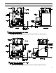
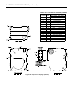
I: GENERAL INFORMATION 'B' 'C' DIA.
I: GENERAL INFORMATION (continued) 'A' 'B' 'C' DIA.
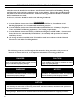
I: GENERAL INFORMATION (continued) TABLE 1: DIMENSIONAL DATA / general information (See figures 1a thru 1D) Dimensions "A" "B" "C" Approx. Water Content - Gallons CL3 17-3/8" 8-1/4" 5-7/8" 16 14.33 CL4 22-3/8" 10-7/8" 6-7/8" 20 20.90 CL5 27-3/8" 13-3/8" 7-7/8" 24 27.46 Boiler Model Heat Transfer Surface Area - Sq. Ft. Maximum Working Pressure: Steam: 15 PSI; Water: 30 PSI Shipped Standard from Factory, 50 PSI Optional Table 2: rating data Boiler Model No.
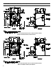
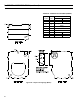
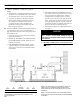
I: GENERAL INFORMATION (continued) Table 3A: Purpose of Tappings (Water) Tapping Location Size, NPT A 1½” B ½” C ¼” D 1½” Supply E 1½” Optional Return Return Limit Well Plug Temperature/Pressure Gauge F ¾” G ¾” N/A H ¾” N/A Limit Well I ¾” N/A DHW Inlet Figure 2A: Purpose of Tappings (Water) 8 Purpose Less Heater With Heater Relief Valve DHW Outlet
I: GENERAL INFORMATION (continued) Table 3B: Purpose of Tappings (Steam) Purpose Tapping Size, Location NPT Less Heater With Heater A B C D E F G H I J K L M N O P 1½” ½” ¼” 3” 1½” ¾” ¾” ¾” ¾” ¾” ¾” ½” ½” 1” ½” 1½” Return Pressure Limit Pressure Gauge Supply Optional Return Relief Valve N/A DHW Outlet N/A Limit Well N/A DHW Inlet Drain LWCO Water Gauge Glass Water Gauge Glass Indirect Water Heater Supply Indirect Water Heater Limit Surface Blowoff Figure 2B: Purpose of Tappings (Steam) 9
II: Pre-Installation A. INSPECT SHIPMENT carefully for any signs of damage. 1. All equipment is carefully manufactured, inspected and packed. Our responsibility ceases upon delivery of crated boiler to the carrier in good condition. 2. Any claims for damage or shortage in shipment must be filed immediately against the carrier by the consignee. No claims for variances from, or shortage in orders, will be allowed by the manufacturer unless presented within sixty (60) days after receipt of goods. B.
II: Pre-Installation (continued) WARNING Adequate combustion and ventilation air must be provided to assure proper combustion and to maintain safe ambient air temperatures. Do not install boiler where gasoline or other flammable vapors or liquids, or sources of hydrocarbons (i.e. bleaches, fabric softeners, etc.) are used or stored. 1. Determine volume of space (boiler room).
III: Installation Instructions A. REMOVE CRATE 1. Remove all fasteners at crate skid. 2. Lift outside container and remove all other inside protective spacers and bracing. Remove miscellaneous steam or water trim carton. B. REMOVAL OF BOILER FROM SKID 1. Boiler is secured to base with 4 carriage bolts, 2 on left side and 2 on right side. See Figure 4. Remove all bolts. models, attached to the burner. Select the proper oil nozzle for the installation.
III: Installation Instructions (continued) l. Inspect Beckett head setting on left side of burner by insuring the line on the label MB(L1) or the blue line MD(V1) are aligned, readjust if necessary. Refer to Figure 26. m. Tighten knurled nut. ii. Remove existing nozzle from nozzle adapter. iii. Insert the proper NOZZLE into NOZZLE ADAPTER and tighten securely (Do not cover tighten), refer to Table 14B (at rear of this manual). n. Swing igniter closed, rotate tabs and tighten two (2) igniter screws. iv.
III: Installation Instructions (continued) Figure 9: Riello Pump Connections and Port Identification g. Pump Connections and Port Identification, refer to Figure 9. This burner is shipped with the oil pump set to operate on a single line system. To operate on a two-line system the bypass plug must be installed. WARNING: Do not operate a single line system with the by-pass plug installed. Operating a single line system with the by-pass plug installed will result in damage to the pump shaft seal.
III: Installation Instructions (continued) b. On water boilers with rear tankless heater, the factory wired Warm Start Boiler Control was not installed in heater. Locate 3/4" NPT immersion well, apply sealant, thread into 3/4" NPT tapping on tankless heater and tighten with wrench. Apply heat transfer paste (not furnished) to limit sensor and fully insert limit sensor into immersion well such that the tip on the limit sensor touches the bottom of the immersion well. See Figure 10.
Figure 11A: Recommended Water Piping for Circulator Zoned Heating System - Supply Side Circulator III: Installation Instructions (continued)
Figure 11B: Recommended Water Piping for Zone Valve Zoned Heating System - Supply Side Circulator III: Installation Instructions (continued)
Figure 12: Recommended Boiler Piping for Gravity Return Steam Boiler III: Installation Instructions (continued)
III: Installation Instructions (continued) • If the system contains hidden supply or return piping (hidden behind walls, buried in concrete, etc.) pressure test this piping to assure there are no leaks. ii. Repair any leaks in the system. iii. Install accurate water meter on the fresh water supply to the boiler. NOTICE Do not use softened water in steam boilers. Accelerated boiler corrosion will result. Tie in fresh water supply to the boiler upstream of a water softener.
III: Installation Instructions (continued) of 3’ away from the inlet so that the regulator is not subjected to excess temperatures that may occur during “off” periods when it is possible for heat to be conducted back through the supply line. The flow regulator also limits the flow of supply water regardless of inlet pressure variations in the range of 20 to 125 psi.
III: Installation Instructions (continued) Figure 15: Indirect Water Heater Piping on CL Series Steam Boiler a. CL SERIES WATER BOILER - Figures 11A and 11B show indirect water heater piping on typical hot water heating system. Boiler piping is the same as for any two-zone system. Figures 11A and 11B show circulator zoning, which is usually preferred for indirect water heaters.
III: Installation Instructions (continued) Figure 17: Proper and Improper Locations of Draft Regulator lower stack temperature and less dilution air can, in some cases, contribute to the condensing of small amounts of water vapor in the chimney. Such condensation, when it occurs, can cause chimney deterioration. In extreme cases, condensed water may be visible on the outside of the breeching or chimney.
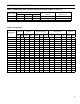
III: Installation Instructions (continued) Table 5: single stage units (3450 rpm) two pipe systems Lift "H" (See Figure) 0' 1' 2' 3' 4' 5' 6' 7' 8' 9' 10' 11' 12' 13' 14' Maximum Length of Tubing "H" + "R" (See Figure) 3/8" OD 1/2" OD Tubing (3 GPH) Tubing (3 GPH) 84' 78' 73' 68' 63' 57' 52' 47' 42' 36' 31' 26' 21' ----- 100' 100' 100' 100' 100' 100' 100' 100' 100' 100' 100' 100' 83' 62' 41' Table 6: two-stage units (3450 rpm) two-pipe systems Lift "H" (See Figure) Maximum Length of Tubing "H" + "R" (Se
IV: Electrical DANGER Positively assure all electrical connections are unpowered before attempting installation or service of electrical components or connections of the boiler or building. Lock out all electrical boxes with padlock once power is turned off. WARNING Failure to properly wire electrical connections to the boiler may result in serious physical harm. Electrical power may be from more than one source. Make sure all power is off before attempting any electrical work.
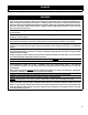
Refer to Figure 24 for Schematic wiring diagram of appropriate burner and oil primary control option Figure 20: Schematic Wiring Diagram, without Tankless Heater, Cold Start Control (Beckett and Riello Burners) IV: Electrical (continued)
Refer to Figure 24 for Schematic wiring diagram of appropriate burner and oil primary control option Figure 21: Schematic Wiring Diagram, with Tankless Heater, Warm Start Control (Beckett and Riello Burners) IV: Electrical (continued)
N 1 2 1-3 BK WH Jumper Figure 22: Schematic Wiring Diagram, Steam Boilers With or Without Tankless Heater, McDonnell & Miller PS-801 Probe LWCO, Beckett AFG Burner H-C B H 5 RD Lettered Terminals Numbered Terminals Wire Color McDonnell & Miller PS-801 Terminals May Be Lettered or Numbered as Follows: Refer to Figure 24 for Schematic wiring diagram of appropriate burner and oil primary control option IV: Electrical (continued)
Refer to Figure 24 for Schematic wiring diagram of appropriate burner and oil primary control option Figure 23: Schematic Wiring Diagram, Steam Boilers with or without Tankless Heater, McDonnell & Miller PS-801 Probe LWCO, Riello 40 Burner IV: Electrical (continued)
IV: Electrical (continued) NOTE: APPLY THIS BURNER SCHEMATIC TO APPROPRIATE STEAM OR WATER BOILER CONTROL SCHEMATIC, REFER TO FIGURES 20 THRU 23 NOTE: APPLY THIS BURNER SCHEMATIC TO APPROPRIATE STEAM OR WATER BOILER CONTROL SCHEMATIC, REFER TO FIGURES 20 THRU 23 Figure 24: Schematic Wiring Diagrams For All Burner Options w/Various Oil Primary Controls 29
V: system start-up WARNING All boilers equipped with burner swing door have a potential hazard which can cause severe property damage, personal injury or loss of life if ignored. Before opening swing door, turn off service switch to boiler to prevent accidental firing of burner outside the combustion chamber. Be sure to tighten swing door fastener completely when service is completed. A. ALWAYS INSPECT INSTALLATION BEFORE STARTING BURNER. 1.
V: system start-up (continued) 3. STEAM BOILERS: c. OPEN ALL OIL LINE VALVES. With an PA404A Pressure Limit - set cut-out pressure (MAIN scale) on the pressure limit for (1) PSI and differential pressure (DIFF.) for .5 PSI. These pressures may be varied to suit individual requirements of the system. d. Attach a plastic hose to fuel pump vent fitting and provide a pan to catch the oil. e. OPEN FLAME OBSERVATION PORT COVER on burner swing door. 3. Riello Burners 4.
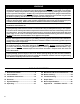
V: system start-up (continued) the fire is -0.02”. Use a smoke tester and adjust air for minimum smoke (not to exceed #1) with a minimum of excess air. Make final check using suitable instrumentation to obtain a CO2 of 11.5 to 12.5% with draft of -0.02” (water gauge) in fire box. These settings will assure a safe and efficient operating condition. If the flame appears stringy instead of a solid fire, try another nozzle of the same type. Flame should be solid and compact.
Figure 26: "L1" and "V1" Head Electrode Positioning and Gun Setting (Beckett AFG) V: system start-up (continued)
V: system start-up (continued) Figure 27: Cad Cell Location H. CHECK FOR CLEAN CUT OFF OF BURNER. 1. AIR IN THE OIL LINE between fuel unit and nozzle will compress when burner is on and will expand when burner stops, causing oil to squirt from nozzle at low pressure as burner slows down and causing nozzle to drip after burner stops. Usually cycling the burner operation about 5 to 10 times will rid oil line of this air. 2. IF NOZZLE CONTINUES TO DRIP, repeat Paragraph H, Step 1 above.
V: system start-up (continued) v. zero each time a call for heat is successfully completed. T-T Jumper: Select models have preinstalled T-T jumper. Do not remove jumper. Note: Do not remove "T-T" jumper unless wiring diagram indicates a direct connection from thermostat and/or tankless heater aquastat control to the oil burner primary control's "T-T" terminal. Refer to appropriate wiring diagram, see Figure 20, 21, 22 or 23. vi.
V: system start-up (continued) 4. CHECK HIGH LIMIT Close boiler drain and refill to normal water line. Burner should automatically restart during fill. Lower thermostat setting. a. Adjust system thermostat(s) to highest setting. b. Allow burner to run until boiler water temperature exceeds high limit setting. The burner should shut down and circulators continue running. b. Water Boiler Refer to Appendix "A" at the rear of this manual. 6.
VI: OPERATING A. WATER BOILERS SEQUENCE OF OPERATION 1. Water Boilers Without Tankless Heaters (Cold Start), Sequence Of Operation: a. The CL Boiler is equipped with an Intelligent Oil Boiler Control (Cold Start Boiler Control). The boiler control replaces the traditional electronic aquastat and circulator relays and adds energy saving thermal purge features. Energy is saved by starting the circulator and delaying the burner start when there is residual heat available in the boiler. b.
VI: OPERATING (continued) d. If the thermostat is not satisfied and the Operating Setpoint (SP) is reached the system circulator will continue to operate and the burner will stop. When the boiler water temperature drops below the setpoint less the differential setting the burner will restart. Press and release the “I” key on the Boiler Control to change from one parameter to the next. Each setting will alternately flash between the relevant display code and its corresponding value.
VI: OPERATING (continued) Cold Start Boiler Control Adjustment Mode Options HL_ HdF ZC_ Or_ PP_ St_ Pt_ f-C bac 140-240°F 10-30°F dh, ZR or ELL 0-10 minutes 2-20 minutes 140 - 180°F On or Off F or C Adjust High Limit Setting Adjust High Limit Differential ZC and ZR Terminal Function Pump Overrun Time Pump Pre-purge Time Start Temperature Priority Time Select degrees F or C Mode Back to Operating Mode Warm Start Boiler Control Adjustment Mode Options HL_ LL_ 140-240°F 110-220°F Ldf 10-25°F ZC_ Or_ P
VI: Operating (continued) Table 8: circulator pre-purge time example, parameter pp_= 2 minutes Call for Heat ZC and ZR Terminal Boiler Function Temp. (ZC_) i. ZC and ZR Terminal Function (ZC_) The boiler control allows configuration of the ZC output functionality to help the CL integrate into each installation more effectively. The ZC output can be connected to a domestic hot water circulator or a second heating zone circulator or be used to enable pumps in a warm start application.
VI: Operating (continued) Table 10: zone request, parameter zc_= zr Call for Heat T-T ZR Input Input off on on off off off on on Circulator Status C1 ZC Output Output off on on off off off on on ii. When is set equal to Zone Request () When there is no IWH the Cold Start Boiler Control “ZC” output may be configured to control a second heating zone. This is particularly helpful when the home uses only two heating zones. The boiler control replaces the need for a two circulator zone panel.
VII: Maintenance and Service Instructions A. MAINTENANCE OF LOW WATER CUTOFF DEVICES WARNING Probe and float type low water cut-off devices require annual inspection and maintenance. 1. Although these devices are solid state in their operation, the probe is exposed to possible contamination in the boiler water and subject to fouling. 2. It is important to physically remove the probe from the boiler tapping annually and inspect that probe for accumulation of scale or sediment. 3.
VII: Maintenance and Service Instructions (continued) NOTICE Check with local authorities or consult local water treatment services for acceptable chemical cleaning compounds. iii. Start burner and operate sufficiently to boil the water without producing steam pressure. Boil for about 5 hours. Open boiler feed pipe sufficiently to permit a steady trickle of water from the surface blow-off pipe.
VII: Maintenance and Service Instructions (continued) 2. WATER BOILERS: a. Filling of boiler and system. General — In a hot water heating system, the boiler and entire system (other than the expansion tank) must be full of water for satisfactory operation. Water should be added to the system until the boiler pressure gauge registers 12 psi. To insure that the system is full, water should come out of all air vents when opened. b. Boiling Out of Boiler and System.
VII: Maintenance and Service Instructions (continued) 2. Spray inside surfaces with light lubricating or crankcase oil using gun with extended stem so as to reach all corners. 3. With steam boilers, at end of season add sufficient water to fill boiler to top of water column and leave it that way until fall when water should be drained again to proper level. If, at this time, boiler water is dirty, drain water, flush out boiler, and refill with clean water to prescribed water level. 4.
VIII: Boiler Cleaning (continued) Figure 31: Cleaning of Boiler Flueways 46
Important Product Safety Information Refractory Ceramic Fiber Product Warning: The Repair Parts list designates parts that contain refractory ceramic fibers (RCF). RCF has been classified as a possible human carcinogen. When exposed to temperatures about 1805°F, such as during direct flame contact, RCF changes into crystalline silica, a known carcinogen. When disturbed as a result of servicing or repair, these substances become airborne and, if inhaled, may be hazardous to your health.
IX: Troubleshooting A. COMBUSTION 1. NOZZLES — Although the nozzle is a relatively inexpensive device, its function is critical to the successful operation of the oil burner. The selection of the nozzle supplied with the CL boiler is the result of extensive testing to obtain the best flame shape and efficient combustion. Other brands of the same spray angle and spray pattern may be used but may not perform at the expected level of CO2 and smoke.
IX: Troubleshooting (continued) B. OIL PRIMARY CONTROL (Oil Primary) 1. Burner (Oil Primary) will not come on. a. No power to Oil Primary. b. Oil Primary is in lockout or restricted mode. Press reset button for one (1) second to exit lockout. If control has recycled three times within the same call for heat, it will enter into restricted mode. To reset from restricted mode, refer to Section V, Paragraph I, Step 2 for details. c. CAD cell seeing light. d. CAD assembly defective. e.
IX: Troubleshooting (continued) b. If the Boiler Control detects an error it will flash "" (boiler control error) followed by a number. Use this text and number to identify the boiler problem and corrective action in Table 13 below.
X: Repair Parts All CL™ Series repair parts may be ordered through New Yorker Boiler Co., Inc., or its authorized distributors. Bare Boiler Assembly (Exploded View) Should you require assistance in locating a New Yorker Distributor in your area, or have questions regarding the availability of New Yorker products or repair parts, please contact: New Yorker Boiler Co., Inc., P.O.
X: Repair Parts (continued) Item Description No. Boiler Size / Quantity CL3 CL4 CL5 Part No. Bare Boiler Assembly 1 Front Section (Non-Htr.), Machined Water ---(OR)--Front Section (Non-Htr.), Machined Steam 1 1 1 2 Center Section 1 2 3 3 4 Rear Section (Non-Htr.), Machined Water ---(OR)--Rear Section (Non-Htr.
X: Repair Parts (continued) Jacket Assembly (Exploded View) Item No. Boiler Size / Quantity Description CL3 CL4 CL5 Part No.
X: Repair Parts (continued) CL3 Thru CL5 Water Boilers - Trim and Controls Item No. Description Boiler Size / Quantity CL3 CL4 CL5 Part No. CL3 Thru CL5 Water Boilers - Trim and Controls 1 1 1 1 1 1 1 1/2" NPT x 1-1/2" Immersion Well, Honeywell 123869A (WL) --- (OR)--3/4" NPT x 3" Immersion Well, Honeywell 123871A (WT) 1 1 1 4 Temperature / Pressure Gauge, ¼" NPT x 2-1/2" Dia. x 1-1/2" Lg. Shank 1 1 1 100282-01 5 6 7 8 9 3/4" NPT x 7-1/4" Lg.
X: Repair Parts (continued) CL3 Thru CL5 Steam Boilers - Trim and Controls Item No. Description Boiler Size / Quantity CL3 CL4 CL5 Part No.
X: Repair Parts (continued) Beckett AFG Burner
BECKETT AFG OIL BURNER PART NOS. FOR CL SERIES BOILERS NOTE: When ordering parts always give the serial and model numbers shown on the boiler and burner. Also provide the name of the part(s) and part number as listed below. Boiler Model Air Tube Combination Beckett's Spec No.
XI: Burner Specifications Table 14A: Beckett Afg Burner Specifications Beckett AFG Firing Rate Boiler Model GPH 1 Settings Head Air (Setting) Shutter Nozzle 3 Air Band GPH x Angle Type 2 p Shipped Pump Pressure CL3-091 0.65 L1 8 0 0.55 x 70B (Delavan) p CL3-105 0.75 L1 6 0 0.65 x 45B (Hago) Installed 140 CL3-140 1.00 L1 10 1 0.85 x 45B (Hago) Installed 140 CL4-126 0.90 L1 7 0 0.75 x 45B (Delavan) Installed 140 CL4-175 1.25 V1(0) 10 1 1.00 x 45B (Hago) 1.
XI: Burner Specifications (continued) RIELLO 40 Series OIL BURNER PART NUMBERS FOR CL SERIES BOILERS Table 14B: Riello Burner Specifications Settings Nozzle Firing Burner Boiler Model Rate Model Air Gate Turbulator GPH x Angle 2 Shipped GPM Type Pump Combustion Head Pressure CL3-105 0.75 40F5 2.60 0 0.60 x 60A (Delavan) Installed 150 CL3-140 1.00 40F5 2.85 2 0.85 x 60W (Delavan) Installed 150 CL4-126 0.90 40F5 2.25 0 0.75 x 60B (Delavan) Installed CL4-175 1.25 40F5 4 4 1.
Appendix A - Low Water Cut Off (LWCO) WARNING DO NOT ATTEMPT to cut factory wires to install an aftermarket Low Water Cut Off (LWCO). Only use connections specifically identified for Low Water Cut Off. In all cases, follow the Low Water Cut Off (LWCO) manufacturer's instructions. When A low water cutoff is required to protect a hot water boiler when any connected heat distributor (radiation) is installed below the top of the hot water boiler (i.e. baseboard on the same floor level as the boiler).
Appendix A - Low Water Cut Off (LWCO) (continued) How to Test Shut off fuel supply. Close shut-off valves in system supply and return piping located in near boiler piping above LWCO as shown in Figure A1. Open drain valve to lower water level until water is below the LWCO probe. It may be necessary to open relief valve seat to allow air into system for the water to drain, close drain valve and relief valve once completed. Generate a boiler demand by turning up thermostat.
SERVICE RECORD DATE SERVICE PERFORMED 62
NEW YORKER BOILER CO., INC. Limited Warranties For Residential Cast Iron Steam Boilers By this Warranty Statement New Yorker Boiler Co., Inc. ("New Yorker") issues limited warranties subject to the terms and conditions stated below.