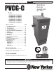
PVCG-C Installation, Operating & Service Manual Installation, Operating and Service Instructions for PVCG-C • Water Boiler • Cast Iron • Induced Draft • Gas Fired Models: • PVCG30CN • PVCG30CP • PVCG40CN • PVCG40CP • PVCG50CN • PVCG50CP • PVCG60CN • PVCG60CP • PVCG70CN • PVCG70CP • PVCG80CN • PVCG80CP Table of Contents 1. 2. 3. 4. 5. 6. 7. 8. 9. 10. 11. 12. 13. 14. Page Product Description. . . . . . . . . . . . . . . . . . 4 Specifications. . . . . . . . . . . . . . . . . . . . . . .
PVCG-C Installation, Operating & Service Manual The Massachusetts Board of Plumbers and Gas Fitters has approved these boilers. See the Massachusetts Board of Plumbers and Gas Fitters website for the latest Approval Code or ask your local Sales Representative. The Commonwealth of Massachusetts requires this product to be installed by a licensed Plumber or Gas fitter.
PVCG-C Installation, Operating & Service Manual ! WARNING Asphyxiation Hazard. Fire Hazard. Explosion Hazard. This boiler requires regular maintenance and service to operate safely. Follow the instructions contained in this manual. • Improper installation, adjustment, alteration, service or maintenance can cause property damage, personal injury or loss of life. Read and understand the entire manual before attempting installation, start-up operation, or service.
PVCG-C Installation, Operating & Service Manual 1 Product Description This is a cast iron gas-fired boiler designed for use in forced hot water heating systems. It is intended for installations where a usable chimney is not available. This boiler is vented using an approved vertical or horizontal AL29-4C stainless steel venting system, which is not included with the boiler. This boiler requires an adequate source of clean combustion air in the boiler room.
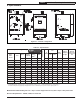
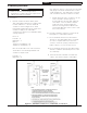
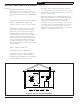
PVCG-C Installation, Operating & Service Manual 2 Specifications Figure 2.1: General Configuration Table 2.2: Specifications Basic Boiler Model (1) (2) Fuel Input (1) Heating Capacity Net AHRI Rating, Water (2) AFUE MBH MBH MBH % # of Sections PVCG-C Space Heating Ratings Connection Size ‘A’ Width (inch) Gas Vent (NPT) (inch) Water Content Approx. Shipping Weight Optional Direct Vent Conversion Kit (gal) (lbs) (PN) PVCG30CN NAT. GAS 70 60 52 85.
PVCG-C Installation, Operating & Service Manual 3 Pre-Installation ! WARNING Carefully read all instructions before installing boiler. Failure to follow all instructions in proper order can cause personal injury or death. A. Inspect shipment carefully for signs of damage. Any claim for damage or shortage in shipment must be filed immediately against carrier by consignee.
PVCG-C Installation, Operating & Service Manual 4 Locating the Boiler ! WARNING Failure to observe the following location requirements could result in a fire, explosion or carbon monoxide (CO) hazard. • A. Clearances: • Provide clearance between boiler jacket and combustible material in accordance with local fire ordinances. Observe minimum clearances shown in Figure 4.1 to avoid potential fire hazard.
PVCG-C 4 Locating the Boiler (continued) F. Do not install this boiler on carpeting. This may cause a fire. G. Do not install this boiler directly on a surface that may get wet. Raise the boiler on a pad. H. Protect ignition system components from sources of water that may spray, drip or rain on them during installation or service. I. Install on level floor. For basement installation provide concrete base if floor is not level or if water may be encountered on floor around boiler.
Installation, Operating & Service Manual PVCG-C 5 Air for Combustion and Ventilation (continued) The National Fuel Gas Code does describe some other acceptable techniques for bringing outdoor combustion air to the boiler room, but these should rarely be needed and are not discussed here. • If the total volume of both the boiler room and the room to which the openings connect is less than 50 cubic feet per 1000 BTU/hr of total appliance input, install a pair of identical openings into a third room.
PVCG-C Installation, Operating & Service Manual 5 Air for Combustion and Ventilation (continued) Example: A 105000 BTU/hr input boiler and a water heater are to be installed in a room measuring 6 ft - 3 in x 7 ft with an 8 ft ceiling. The water heater has an input of 30000 BTU/ hr: Total input in thousands of BTU/hr = (105000 BTU/hr + 30000 BTU/hr) ÷ 1000 = 135 Volume of room = 6.25 ft x 7 ft x 8 ft = 350 ft3 350÷135 = 2.59. Since 2.
PVCG-C Installation, Operating & Service Manual 6 Venting designed to provide a gas tight seal at all joints and seams so that flue gas does not enter the building. Each approved vent system has unique method for installation - do not attempt to mix components from different vent systems. ! WARNING Asphyxiation Hazard. Failure to vent this boiler in accordance with these instructions could cause products of combustion to enter the building resulting in severe property damage, personal injury or death.
Installation, Operating & Service Manual PVCG-C 6A Vent System Design (continued) Table 6.1: Summary Of Venting Options Using Indoor Combustion Air (See Appendix A for Options Using Outdoor Air) Classification Used in this Manual Horizontal Direct Exhaust Vent Option # Vertical Direct Exhaust 1 2 3 4 Illustrated in Figure 6.2 6.2 6.6 6.6 Structure Penetration Wall Wall Roof Roof Listed AL29-4C Stainless Special Gas Vent System (See Table 6.
PVCG-C Installation, Operating & Service Manual 6A Vent System Design (continued) Figure 6.2: Horizontal Direct Exhaust Vent System (Vent Options 1, 2) Figure 6.3: Tee Terminal 109837-01 - 5/20 Figure 6.
PVCG-C Installation, Operating & Service Manual 6A Vent System Design (continued) • If possible, install the terminal on a wall away from the prevailing wind. Reliable operation of this boiler cannot be guaranteed if the terminal is subjected to winds in excess of 40 mph. • The noise level in the vicinity of the terminal is approximately 65 dB (roughly the level of a normal conversation). Avoid positioning the terminal in areas where this might be objectionable. 5.
PVCG-C Installation, Operating & Service Manual 6A Vent System Design (continued) Figure 6.
PVCG-C Installation, Operating & Service Manual 6A Vent System Design (continued) Table 6.7: Permissible Vent Systems And Principle Vent Components MANUFACTURER HEAT FAB VENT SYSTEM SAF-T VENT EZ SEAL PROTECH SYSTEMS INC.
PVCG-C Installation, Operating & Service Manual 6A Vent System Design (continued) Figure 6.9a: Location of Vent Terminal Relative to Windows, Doors and Grades Figure 6.
PVCG-C Installation, Operating & Service Manual 6A Vent System Design (continued) 'Y' 0 - 12" 'X' Max. Overhang NOT PERMITTED 12 - 48" 17 - 29" X minus 7" Greater than 48" 17 - 29" 36" Note: Overhang may not be ventilated if 'Y' is less than 48" Figure 6.
PVCG-C Installation, Operating & Service Manual 6B Removing Boiler From Common Chimney B. Removing Boiler From Common Chimney When an existing boiler is removed from a common venting system, the common venting system is likely to be too large for proper venting of the appliances remaining connected to it.
PVCG-C Installation, Operating & Service Manual 6B Removing Boiler From Common Chimney (continued) f. Une fois qu’il a été déterminé, selon la méthode indiquée ci-dessus, que chaque appareil raccordé au système d’évacuation est mis à l’air libre de façon adéquate. Remettre les portes et les fenêtres, les ventilateurs, les registres de cheminées et les appareils au gaz à leur position originale. g.
PVCG-C Installation, Operating & Service Manual 6C Vent System Assembly (continued) d. On the male end of the pipe, apply a ¼” wide bead of high temperature silicone approximately ½ inch from the male end of the pipe. Also apply a ¼” bead of silicone along the first 2 ½” of the longitudinal weld as shown in Figure 6.11. e. Insert the male end of the pipe into the boiler vent adapter until it bottoms out. f. Apply an additional bead of silicone over the outside of the joint and smooth out (Fig 6.11).
PVCG-C Installation, Operating & Service Manual 7 Water Piping ! WARNING • Failure to properly pipe boiler may result in improper operation and damage to boiler or building. • Install boiler so that the gas ignition system components are protected from water (dripping, spraying, rain, etc.) During appliance operation and service (circulator replacement, etc.). • Operation of this boiler with continuous return temperatures below 120°F can cause severe heat exchanger corrosion damage.
PVCG-C Installation, Operating & Service Manual 7 Water Piping (continued) 6. Low Water Cut-Off (factory supplied) This boiler is equipped with a low water cut-off (LWCO) that prevents the boiler from firing if there is inadequate water in the boiler. This LWCO is an automatic reset type, meaning that it will allow the boiler to restart automatically if the low water condition is corrected.
PVCG-C Installation, Operating & Service Manual 7 Water Piping (continued) 10. Drain Valve - The drain valve is shipped in the boiler parts bag. Install it in the 3/4" tapping as shown in Figure 7.1. B. Piping For Special Situations Certain types of heating systems have additional requirements. Some of the more common variations follow: 1. Indirect Water Heaters - Figure 7.3 shows typical indirect water heater piping. Boiler piping is the same as for any two-zone system. Figure 7.
PVCG-C Installation, Operating & Service Manual 7 Water Piping (continued) If the boiler is to be used in such a system, it must be separated from the oxygenated water being heated with a heat exchanger as shown in Figure 7.4. Consult the heat exchanger manufacturer for proper heat exchanger sizing as well as flow and temperature requirements. All components on the oxygenated side of the heat exchanger, such as the circulator and expansion tank, must be designed for use in oxygenated water.
PVCG-C Installation, Operating & Service Manual 8 Gas Piping ! WARNING • Shut off gas supply before servicing the boiler. • All gas piping must be gas tight. Use thread compound that is listed for gas service on all threaded joints to avoid leaks, which may result in fire or explosion. • Size gas piping, regulators, valves and meters so as to provide an adequate gas flow and pressure to the boiler during operation. Failure to do so may cause poor combustion, noise, injury or death. 1.
PVCG-C Installation, Operating & Service Manual 8 Gas Piping (continued) ! WARNING • If gas pressure in the building is above ½ psig (3.5 kPa), an additional gas pressure regulator is required. Using one additional regulator for multiple gas appliances may result in unsafe boiler operation. The additional regulator must be able to properly regulate gas pressure at the input of the smallest appliance. If the regulator can not do this, two or more additional regulators are required.
PVCG-C Installation, Operating & Service Manual 9 Wiring ! WARNING • All wiring and grounding must be done in accordance with the authority having jurisdiction or, in the absence of such requirements, with the National Electrical Code (ANSI/NFPA 70). In Canada, all wiring and grounding must be done in accordance with the Canadian Electrical Code, Part 1 (CSA C22.1 - latest edition). • Electrical power may be supplied from more than one circuit.
PVCG-C 9 Installation, Operating & Service Manual Wiring (continued) c. Auxiliary Limit Jumper - Used to connect auxiliary limit device. If no such devices are installed, the factory supplied jumper shown in Figures 9.2 and 9.3 must be installed for boiler to operate. d. EnviraCOM - Used to connect an EnviraCom thermostat or other approved EnviraCom device to this boiler. Notice: • When making low voltage connections, make sure that no external power source is present in the thermostat circuits.
9 Installation, Operating & Service Manual PVCG-C 8.
Installation, Operating & Service Manual PVCG-C 9 Wiring (continued) L1 Internal Junction Box Overcurrent Protection / Disconnect (By Installer) L2 Power Supply 120 / 60 / 1 (By Installer) GND Internal Junction Box Service Switch (optional) (By Installer) Boiler Control On/Off System Circulator System Circulator Line Input Neutral P1 3 P1 4 On/Off DHW Circulator DHW Circulator (Supplied by Others) P1 5 On/Off Fan Fan 1 P2 5 2 P2 3 P1 1 24V Transformer Auxiliary Limit Jumper Boiler
PVCG-C Installation, Operating & Service Manual 10 Start-up and Checkout ! WARNING Do not leave the boiler in service if it fails any of the following start-up checks. Doing so may result in fire, explosion, or carbon monoxide (CO) poisoning. ! WARNING • Gas leaks may result in fire or explosion. • Never use a flame to check for gas leaks. • Make sure that the area around the boiler is clear and free from combustible materials, gasoline and other flammable vapors and liquids.
PVCG-C 10 Installation, Operating & Service Manual Start-up and Checkout (continued) Figure 10.
Installation, Operating & Service Manual PVCG-C 10 Start-up and Checkout (continued) appliances on and off. The inlet pressure at the boiler must be within the following limits regardless of what combination of appliances is firing: Inlet Pressure (in. w.c.) Natural Gas LP Gas Minimum 4.5 11.0 Maximum 14.0 14.0 3. If the inlet pressure falls outside of these limits, find and correct the cause of the problem before proceeding further. 4.
PVCG-C 10 Installation, Operating & Service Manual Start-up and Checkout (continued) 2. Ventilate the boiler room, set the high limit to its maximum setting, set the thermostat to call for heat. Allow the boiler to fire for at least an hour or until the odor from the cornstarch has dissipated. 3. Return the high limit and thermostat to their desired settings. T. System Leak Check - After the boiler has operated for at least 30 minutes, check the boiler and heating system piping for leaks.
PVCG-C Installation, Operating & Service Manual 11 Operation A. Controls 1. This boiler uses a proprietary version of the Honeywell S9361A “integrated boiler control” to manage all boiler functions including flame supervision, temperature control, and circulator operation. This control can operate one or two circulator zones without the use of additional relays. 2.
PVCG-C 11 Installation, Operating & Service Manual Operation (continued) Figure 11.2: Boiler Control Menu STATUS MODE: =Current Status (Table 11.3) Press I to enter OPERATING MODE Press and Hold I, ↑, and ↓ for at least 3 sec to enter ADJUSTMENT MODE = Current Boiler Temp.
PVCG-C 11 Installation, Operating & Service Manual Operation (continued) Table 11.3: Status Codes Status # Description Meaning 1 Standby No call for heat or DHW OR Call for heat present , but boiler is in thermal purge (See PP on page 40) OR Call for heat/DHW present but boiler temperature is above high limit (HL) setting. 2 Waiting for Pressure Switch to open Control is confirming that air pressure switch contacts are open before starting fan.
PVCG-C 11 Installation, Operating & Service Manual Operation (continued) Table 11.5: Operating Mode Parameters Parameter # Description Meaning bt Boiler Temperature Current boiler water temperature measured by the control’s sensor. SP Boiler water set point Current target temperature (always the same as the high limit setting unless the outdoor reset card option is installed).
Installation, Operating & Service Manual PVCG-C 11 Operation (continued) ! WARNING Improper adjustments to control parameters could result in unreliable boiler operation, property damage, personal injury, or loss of life. Adjustments should only be made by a qualified heating technician. C. Using Adjustment Mode A list of parameters which can be changed on this control are shown in Table 11.6. To enter Adjustment mode and change parameters: 1. Press and hold I, ↑, ↓ together for at least 3 seconds. 2.
PVCG-C 11 Installation, Operating & Service Manual Operation (continued) rst (Reset) - Used to reset the boiler from a hard lockout (as an alternative to momentarily interrupting power to the control). Pressing the up key will turn rst momentarily to on. When it goes back off (typically within one or two seconds), the control is reset. bAc (Return to Status mode) - Exits adjustment mode.
PVCG-C 11 Installation, Operating & Service Manual Operation (continued) D. Sequence Of Operation 6. The control starts an ignition spark at the pilot and applies 24 volts across the pilot valve (terminals PV and MV/PV on the gas valve). (Refer to Figures 9.3 or 9.4 for Connection and Ladder diagrams) 7. Once the pilot is established, the pilot flame will act as a diode, converting the AC current at the electrode to a half wave DC current at the pilot’s ground strap.
PVCG-C 11 Installation, Operating & Service Manual Operation (continued) E. Safety Control Operation Air Pressure Switch (APS) - The APS proves that the fan is running before allowing the ignition sequence to proceed. Failure of this switch to close is usually the result of a problem with the vent system, such as a blockage, or a problem with the fan.
Installation, Operating & Service Manual SERIES 2E Installation, Operating & Service Manual PVCG-C 12 Service and Maintenance 12 Service and Maintenance Important Product Safety Information: Refractory Ceramic Fiber Product WARNING Some boiler components use materials that contain refractory ceramic fibers (RCF). RCF has been classified as a possible human carcinogen. When exposed to elevated temperatures, RCF may change into crystalline silica, a known carcinogen.
PVCG-C 12 Service and Maintenance (continued) A. Annual Maintenance ! WARNING • Label all wires prior to disconnection when servicing controls. Wiring errors can cause improper and dangerous operation. Verify proper operation after servicing. ATTENTION. Au moment de l'entretien des commandes, étiquetez tous les fils avant de les débrancher. Les erreurs de câblage peuvent nuire au bon fonctionnement et être dangereuses. S'assurer que l'appareil fonctionne adéquatement une fois l'entretien terminé.
PVCG-C 12 Installation, Operating & Service Manual Service and Maintenance (continued) ! WARNING Soot deposits in the flue passages are a sign that the boiler may be operating at high carbon monoxide (CO) levels. After cleaning the boiler of soot deposits, check the CO level in the flue gas to insure that the boiler is operating properly. If it is necessary to check CO, use a combustion analyzer, or other instrument which is designed to measure CO in flue gas.
PVCG-C 12 Installation, Operating & Service Manual Service and Maintenance (continued) C. Service Notes 1. Pressure Switch – This boiler is equipped with a differential pressure switch which makes when there is adequate flue gas flow through the boiler. This switch measures the pressure drop across an orifice plate inside the flue collector; the higher the flue gas flow through this plate, the higher the pressure drop. The N.O.
PVCG-C 12 Installation, Operating & Service Manual Service and Maintenance (continued) Figure 12.3a: Pressure Switch Connections Figure 12.
PVCG-C Installation, Operating & Service Manual 13 Troubleshooting A. Before Troubleshooting The following pages contain troubleshooting tables for use in diagnosing control problems. When using these tables the following should be kept in mind: 1. This information is only meant to be used by a professional heating technician as an aid in diagnosing boiler problems. 2. Where applicable, follow all precautions outlined in the Section 10 (Start-up and Checkout) of the boiler installation manual. 3.
PVCG-C 13 Installation, Operating & Service Manual Troubleshooting (continued) Table 13.
PVCG-C 13 Installation, Operating & Service Manual Troubleshooting (continued) Table 13.1: Faults Without Error Code Present Displayed Codes StA 1 tt OFF dh OFF StA 1 tt On tt On dh On StA 15 StA 6 StA 6 Problem Possible Cause Burners and Circulator Off • • • • Thermostat/s not calling for heat Loose connection in thermostat, zone valve end switch, or zone panel wiring.
REVISIONS REV. 14 Service Parts PVCG-C DATE EN Installation, Operating & Service Manual DESCRIPTION DWN All Service Parts may be obtained through your local New Yorker Boiler wholesale distributor. Should you require assistance in locating a New Yorker Boiler distributor in your area, or have questions regarding the availability of products or service parts, please contact us at (215) 855-8055 or Fax (215) 855-8229. Main burner orifice and pressure switches shown are for sea level configured boilers.
PVCG-C 14 Installation, Operating & Service Manual Service Parts (continued) ! WARNING If base must be replaced, there is a good chance pilot assembly and pilot tubing will need to be replaced as well. Replacement pilot assemblies are shown on page 54. Also check condition of manifold and gas valve and replace if they show any signs of heat, corrosion, or water damage. Key No.
PVCG-C 14 Service Parts (continued) Key No.
3 4 2 PVCG-C 14 1 Installation, Operating & Service Manual A REVISIONS REV. Service Parts (continued) EN DATE DESCRIPTION DWN CHK 3/4/2020 INITIAL RELEASE JP JP D 4A 4G C BK 4C GY 4E 4B 4F 4D 4H B 4G 4F 4G 4F A UNLESS OTHERWISE NOTED: ALL DIMENSIONS IN INCHES. TOLERANCES: X.X ±.1 X.XXX ±.005 X.XX ±.
PVCG-C 14 Service Parts (continued) Key No.
PVCG-C 14 Installation, Operating & Service Manual Service Parts (continued) Key No.
PVCG-C 14 Service Parts (continued) Key No.
PVCG-C 14 Installation, Operating & Service Manual Service Parts (continued) Key No.
PVCG-C 14 Installation, Operating & Service Manual Service Parts (continued) 9A 9B Part Number [Quantity] 60 Key No.
Installation, Operating & Service Manual PVCG-C Appendix A: Direct Vent Installations This Appendix describes how to bring combustion air directly from outside to the boiler (direct venting) using the Direct Vent Conversion Kits shown in Table 2.2. These kits includes an air box and other components needed to route air directly to the combustion chamber, as well as an air intake terminal for horizontal installations.
Installation, Operating & Service Manual PVCG-C Appendix A (continued) Table A.2: Summary Of Direct Vent Options (See Section 6 for Additional Details on Vent System Installation) Classification Used in this Manual Vent Option # Horizontal Direct Vent 5 Illustrated in Figure 6 Vertical Direct Vent 7 8 9 10 A.3, A.4 A.3, A.4 A.3, A.4 A.6, A.7 A.6, A.7 A.6, A.
PVCG-C Installation, Operating & Service Manual Appendix A (continued) Figure A.4: Horizontal Direct Venting (Vent Options 5-7) 3. Permitted Intake Terminals – a. Horizontal venting applications use the terminal provided with the Direct Vent Conversion Kit. Install this terminal so that it is flush with the wall as shown in Figure A.3. Seal the terminal to the wall using silicone caulk. b.
PVCG-C Installation, Operating & Service Manual Appendix A (continued) Figure A.5: Horizontal Terminal Offsets Figure A.
Installation, Operating & Service Manual PVCG-C Appendix A (continued) D. Air Intake System Assembly - 4. If PVC is used for the intake system, the PVC will fit over the outside of the air intake collar on the boiler. Secure the PVC pipe directly to the boiler using a single sheet metal screw and seal the outside of the joint with silicone sealant. 1. If PVC piping is used, use PVC cement to assemble the PVC intake system components. 2.
PVCG-C Installation, Operating & Service Manual Appendix B: Instructions for High Altitude Installations (US Only) These instructions apply only to the following altitude ranges: Sea Level - 2000ft, 2001-10,200ft These instructions contain specific information to setup your boiler to ensure proper operation. As with most gas appliances, special consideration must be given to when this boiler is installed at altitudes above 2000ft.
PVCG-C Installation, Operating & Service Manual Appendix B (continued) Figure B.2: Air Intake Terminal (Installed on Air Intake Collar) ! WARNING • Safe operation of this boiler depends upon the use of the correct burner orifice AND pressure switch for the altitude at which the boiler is to be installed. See Table B.1 for the correct configuration. Failure to properly configure this boiler for the installation altitude could cause personal injury or death due to carbon monoxide (CO) poisoning.
PVCG-C Appendix C: Installation, Operating & Service Manual Low Return Water Temperatures Thermal Shock: Cast iron boilers are very robust. 110°F and below return water temperatures will not cause thermal shock to New Yorker Boiler castings. Condensation is a different matter: Cast iron boilers will tolerate intermittent periods of condensation but are not designed for extended condensation periods. Water temperatures below 120°F cause condensation that damage cast iron, burners and other components.
PVCG-C Installation, Operating & Service Manual Appendix C (continued) Primary-Secondary Pumping: This is an improvement over simple by-pass piping to reduce condensation. Again this is a fixed system. It can not adapt to variations in temperature and flow. Best Alternative: New Yorker Boiler offers a system by-pass kit [part number 107795-01] that addresses these situations. A strap on temperature sensor measures boiler inlet temperatures.
PVCG-C Installation, Operating & Service Manual Appendix D: Special Requirements For Side-Wall Vented Appliances In The Commonwealth of Massachusetts IMPORTANT The Commonwealth of Massachusetts requires compliance with regulation 248 CMR 4.00 and 5.00 for installation of side-wall vented gas appliances as follows: 1.
PVCG-C Installation, Operating & Service Manual SERVICE RECORD DATE 109837-01 - 5/20 SERVICE PERFORMED 71
PVCG-C Installation, Operating & Service Manual Notes New Yorker Boiler Co. Inc. P.O. Box 3005 Lancaster, PA 17604-3005 www.newyorkerboiler.