
Install Instructions


12
109837-01 - 5/20
PVCG-C
Installation, Operating & Service Manual
NOTICE: Do not exceed maximum vent system length. Refer to Table 6.1 in this section for maximum vent
system length. Use only vent terminals and terminal locations shown in Tables 6.1, and 6.6 and related Figures
in this section.
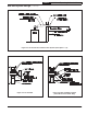
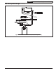
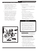
4. Horizontal Vent Terminal Location - Observe
the following limitations on the vent terminal
location (also see Figure 6.9):
• Terminal must be at least 4 feet below
or 4 feet horizontally from any operable
window, door, or gravity air inlet into the
building.
• The bottom of the terminal must be at least
12” above the normal snow line. In no case
should it be less than 12” above grade
level.
• Do not locate the vent terminal over a
public walkway.
• The bottom of the terminal must be at
least 3 feet above any forced air inlet
located within 10 feet.
• Minimum clearance from electric meters,
gas meters, regulators, and relief
equipment:
United States - Minimum 4 ft (1.22 m)
horizontally from and in no case above or
below, unless a 4 ft (1.22 m) horizontal
distance is maintained.
Canada - Minimum 6 ft (1.83 m)
horizontally from and in no case above
or below, unless a 6 ft (1.83 m) horizontal
distance is maintained.
• Do not locate the terminal under decks or
similar structures.
• In general, the top of the vent terminal
must be at least 4ft below eves, soffits,
and other overhangs. If the overhang is
unventilated and if the terminal can extend
beyond the overhang while meeting the
stick-out requirements shown in Figure
6.3 or 6.4, this vertical clearance can be
reduced to as little as 12”. See Figure 6.9c.
Note that flue gas condensate will form
under such overhangs and construction in
this area must be appropriately protected.
• Terminal must be at least 12” from an
inside corner. Exception: if window and/or
air inlet is within four (4) feet of an inside
corner, then vent terminal must be at least
six (6) feet from adjoining wall of inside
corner.
• Under certain conditions, water in the
flue gas may condense on the structure
in areas around the terminal. If these areas
are made of materials subject to damage
from flue gas condensate or ice, they
should be protected.
6A Vent System Design (continued)
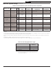
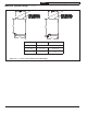
Table 6.1: Summary Of Venting Options Using Indoor Combustion Air
(See Appendix A for Options Using Outdoor Air)
Classification Used in this Manual Horizontal Direct Exhaust Vertical Direct Exhaust
Vent Option # 1 2 3 4
Illustrated in Figure 6.2 6.2 6.6 6.6
Structure Penetration Wall Wall Roof Roof
Material Listed AL29-4C Stainless Special Gas Vent System (See Table 6.7)
Nominal Diameter (inches) 3 4
3
3 4
Maximum
Vent Length
PVCG30C thru
PVCG60C
50 ft Not Permitted 50 ft Not Permitted
PVCG70C 15 ft 50 ft
15 ft 50 ft
PVCG80C Not Permitted 40 ft
Not Permitted 40 ft
Terminal Option A 3" Tee
1
4" Tee
1
3" Cap
1
4" Cap
1
Terminal Option B Miter + 45 Elbow
2
Not Permitted Not Permitted Not Permitted
1. Tee or Cap terminal is supplied by the installer and is compatible with special gas vent system. See Table 6.7 for details.
2. Suitable for use on PVCG30C thru PVCG60C only. Miter terminal is part #8110701 and is purchased separately. 45° Elbow is
by special gas vent manufacturer.
3. PVCG70C is factory supplied with a 3" adaptor. A 3 x 4 increaser compatible with the special gas vent system is required when these
models are vented using 4" pipe. When used, this increaser must be the first fitting installed on the boiler adaptor.