
Install Instructions


14
109837-01 - 5/20
PVCG-C
Installation, Operating & Service Manual
• If possible, install the terminal on a wall
away from the prevailing wind. Reliable
operation of this boiler cannot be
guaranteed if the terminal is subjected to
winds in excess of 40 mph.
• The noise level in the vicinity of the
terminal is approximately 65 dB (roughly
the level of a nor mal conversation). Avoid
positioning the terminal in areas where this
might be objectionable.
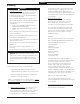
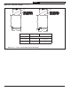
5. Terminal Offsets - Tee terminals may be offset
by as much as 7 ft as shown in Figure 6.5.
This sometimes helps maintain the 12”
minimum clearance required above the
snow line. The extra two elbows and
the section of vertical pipe on the outside
of the building must be counted when
checking that the maximum vent
pipe length is not exceeded. When
this offset is used, the horizontal section of
vent pipe must be pitched away from the
outside so that condensate cannot collect in
the lower offset elbow.
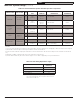
6. Permitted Terminals for Vertical Venting (Vent
Options 3, 4) - Terminals used on these
systems are caps provided by the vent
system manufacturer. Vent manufacturer part
numbers for these caps are shown in Table
6.7.
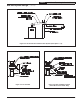
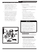
7. Vertical Vent Terminal Locations (Vent Options
3, 4) - The lowest discharge opening on
the cap must be at least 2 feet above any
object located within 10 feet. (Figure 6.6)
8. Wall Thimbles – Wall thimbles are required
where the vent pipe passes through
combustible walls with less than the required
clearance shown in Figure 4.1 or as required
by local codes. Vent manufacturer’s wall
thimble part numbers are shown in Table 6.7.
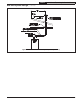
9. Condensate Traps and Pitch of Horizontal
Piping – All installations require a condensate
trap. Pitch all horizontal piping ¼” per
foot so that any condensate or rain water in
the vent system will run towards this trap. Vent
manufacturer’s part numbers for suitable traps
are shown in Table 6.7.
10. Fire Stops and Wall Thimbles – Use
fire stops where required by code or by
the vent system manufacturer. Consult vent
system manufacturer’s literature for
information on suitable fire stops.
11. Supports - Vertical and horizontal sections of
vent pipe must be properly supported. See
the Vent System assembly section of this
manual for more information.
12. Access for Inspection - Refer to the vent
manufacturer's instructions for access
requirements to vent components.
Figure 6.5: Optional Terminal Offset for Horizontal Vent Systems
6A Vent System Design (continued)