
Install Instructions


16
109837-01 - 5/20
PVCG-C
Installation, Operating & Service Manual
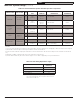
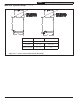
Table 6.7: Permissible Vent Systems And Principle Vent Components
MANUFACTURER VENT SYSTEM SIZE
CONDENSATE
TRAP
WALL
THIMBLES
HORIZONTAL
TERMINATION
VERTICAL
TERMINATION
HEAT FAB
SAF-T VENT
EZ SEAL
3
9321
(NOTE 2)
7393GC
7393GCS
5391CI
TEE: 7390TEE
5300CI
4
9421
(NOTE 2)
7493GC
7493GCS
5491CI
TEE: 7490TEE 5400CI
PROTECH
SYSTEMS
INC.
FASNSEAL
3 FSHDT3 FSWT3 TEE: FSTT3 FSRC3
4
FSHDT4
OR FSCD4
(NOTE 3)
FSWT4 TEE: FSTT4 FSRC4
Z-FLEX
SVE
SERIES III
(“Z-VENT III”)
3 SVEDWCF03 2SVSWTEF03 TEE: 2SVSTTF03 2SVSRCF03
4 SVEDWCF04 2SVSWTEF04 TEE: 2SVSTTF04 2SVSRCF04
METAL-FAB CORR/GUARD
3 CGSWDS(3”) CGSWWPK(3”) TEE: CGSWTTM(3”) CGSWC(3”)
4 CGSWDS(4”) CGSWWPK(4”) TEE: CGSWTTM(4”) CGSWC(4”)
NOTES:
1) See vent system manufacturer’s literature for other part numbers that are required such as straight pipe, elbows, firestops and vent supports.
2) All Heat Fab condensate traps shown may be installed in vertical or horizontal run.
3) Protech FSCD4 condensate trap may be installed in a vertical or horizontal run. All other Protech traps must be installed in a horizontal run
only.
4) Metal-Fab CGSWDS condensate traps may only be installed in a horizontal run.
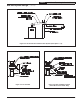
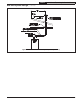
5) 8110701 Miter terminal may be used as shown in Figure 6.4. 45° elbow is supplied by vent system manufacturer.
Table 6.8: Vent Fitting Equivalent Length
VENT FITTING EQUIVALENT
LENGTH (ft)
*
3” 90 ELBOW 5.5
3” 45 ELBOW 4.0
4” 90 ELBOW 8.0
4” 45 ELBOW 4.5
* Where different equivalent lengths are published by the
vent system manufacturer, these may be used in lieu of the
values shown in Table 6.8
6A Vent System Design (continued)