
Install Instructions


20
109837-01 - 5/20
PVCG-C
Installation, Operating & Service Manual
f. Une fois qu’il a été déterminé, selon la
méthode indiquée ci-dessus, que chaque
appareil raccordé au système
d’évacuation est mis à l’air libre de façon
adéquate. Remettre les portes et les
fenêtres, les ventilateurs, les
registres de cheminées et les appareils au
gaz à leur position originale.
g. Tout mauvais fonctionnement du système
d’évacuation commun devrat être corrigé
de façon que l’installation soit conforme
au National Fuel Gas Code, ANSI Z223.1/
NFPA 54 et (ou) aux codes d’installation
CAN/CSA-B149.1. Si la grosseur d’une
section du système d’évacuation doit
être modifiée, le système devrait être
modifié pour respecter les valeurs
minimales des tableaux pertinents de
l’appendice F du National Fuel Gas
Code, ANSI Z223.1/NFPA 54 et (ou) des
codes d’installation CAN/CSA-B149.1.
CAUTION
Approved vent systems rely on gaskets for proper
sealing. Take the following precautions:
• Make sure that gasket is in position and
undamaged in the female end of the pipe.
• Make sure that both the male and female pipes
are free of damage prior to assembly.
• After making the vent adapter connection,
only cut vent pipe as permitted by the vent
manufacturer in accordance with their
instructions. When pipe is cut, cut end must be
square and carefully deburred prior to
assembly.
!
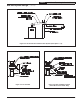
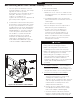
Figure 6.10: Installation of Vent Adapter
C. Vent System Assembly
1. General Assembly Notes:
a. Where the use of “silicone” is called for in the
following instructions, use GE RTV 106 for the
vent adapter.
b. Longitudinal welded seams should not be
placed at the bottom of horizontal sections of
exhaust pipe.
c. Do not drill holes in vent pipe.
d. Do not attempt to mix vent components of
different vent system manufacturers.
e. In some cases, there are differences
between the vent system installation
instructions in this manual and those in
the vent system manufacturer’s manual.
Where such differences exist, this manual
takes precedence over the vent system
manufacturer’s manual.
2. Vent Adapter Installation – The vent adapter is
shipped loose. Mount the vent adapter to the
fan outlet on the boiler as shown in Figure 6.10
using the two stainless steel screws provided.
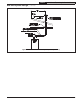
3. Connection of Vent Pipe to Vent Adapter
a. If using Heat Fab Saf-T- Vent, cut the
spigot off of the first piece of pipe using
a sharp pair of aviation snips, an
abrasive cut-off, or a plasma cutter. The male
end of the pipe made by other vent system
manufacturers should slip into the vent
adapter without modification.
b. Remove the hose clamp shipped on the
vent adapter. Bend the three hose clamp
tabs on this adapter outward slightly.
c. Clean the exterior of the male end of the
first piece of pipe and the inside of the vent
adapter on the boiler with an alcohol pad.
6B Removing Boiler From Common Chimney (continued)