
Install Instructions


21
109837-01 - 5/20
PVCG-C
Installation, Operating & Service Manual
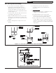
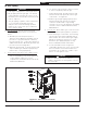
d. On the male end of the pipe, apply a ¼”
wide bead of high temperature silicone
approximately ½ inch from the male end of
the pipe. Also apply a ¼” bead of silicone
along the first 2 ½” of the longitudinal weld as
shown in Figure 6.11.
e. Insert the male end of the pipe into the boiler
vent adapter until it bottoms out.
f. Apply an additional bead of silicone over the
outside of the joint and smooth out (Fig 6.11).
Also apply silicone over the seams in the vent
adapter.
g. Replace and tighten the clamp on the vent
adapter.
Figure 6.11: Connection of First Vent Pipe to Boiler Vent Adapter
4. Complete the rest of the vent system in
accordance with the vent manufacturer’s
instructions.
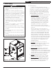
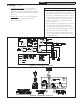
5. Condensate Traps:
a. Trap must have the basic configuration shown
in Figure 6.12. All tubing is 3/8 I.D.
b. All drain tubing must be acid resistant.
c. At least the first 6 inches of tubing must be
silicone with a 300F temperature rating.
d. Pipe condensate to a drain or other suitable
location. Make sure that condensate disposal
method is in accordance with local regulations.
Ensure condensate is not subjected to freezing
temperatures.
Figure 6.12: Condensate Trap/Drain Detail
6C Vent System Assembly (continued)