
Install Instructions


22
109837-01 - 5/20
PVCG-C
Installation, Operating & Service Manual
7 Water Piping
WARNING
• Failure to properly pipe boiler may result in
improper operation and damage to boiler or
building.
• Install boiler so that the gas ignition system
components are protected from water (dripping,
spraying, rain, etc.) During appliance operation
and service (circulator replacement, etc.).
• Operation of this boiler with continuous return
temperatures below 120°F can cause severe
heat exchanger corrosion damage.
• Operation of this boiler in a system having
significant amounts of dissolved oxygen can
cause severe heat exchanger corrosion
damage.
• Do not use toxic additives, such as automotive
antifreeze, in a hydronic system.
• Pipe relief valve discharge to a safe location.
The safety relief valve may discharge scalding
hot water.
• Do not install a valve in the safety relief valve
discharge line.
• Do not move relief valve from factory specified
location.
• Do not plug relief valve discharge. Blocking the
safety relief valve may result in boiler explosion.
!
A. Standard Piping
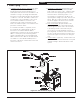
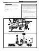
Figure 7.2 shows typical boiler system
connections on a single zone system. Additional
information on hydronic system design may be
found in the I=B=R Guide RHH published by
the Air-Conditioning, Heating and Refrigeration
Institute (AHRI). The components in this system
and their purposes are as follows:
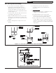
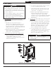
1. Safety Relief Valve (Required) - Mount the relief
valve on the left side of the boiler as shown
in Figure 7.1 using the 1-1/4 supply water
manifold provided with the boiler. The relief
valve shipped with the boiler is set to open
at 30 psi. This valve may be replaced with
one having a pressure up to the “Maximum
Allowable Working Pressure” shown on the
rating plate. If the valve is replaced, the
replacement must have a relief capacity in
excess of the minimum relief valve capacity for
the boiler.
Pipe the discharge of the relief valve to a
location where water or steam will not create a
hazard or cause property damage if the valve
opens. The end of the discharge pipe must
terminate in an unthreaded pipe. If the relief
valve discharge is not piped to a drain it must
terminate at least 6 inches above the floor. Do
not run relief valve discharge piping through an
area that is prone to freezing. The termination
of the relief valve discharge piping must be
in an area where it is not likely to become
plugged by debris.
2. Circulator (Required) - The circulator is
shipped loose with the boiler. If the circulator
is mounted in the supply it should be
positioned just downstream of the expansion
tank as shown in Figure 7.2.
3. Expansion Tank (Required) - If this boiler is
replacing an existing boiler with no other
changes in the system, the old expansion tank
can generally be reused. If the expansion tank
must be replaced, consult the expansion tank
manufacturer’s literature for proper sizing.
4. Fill Valve (Required) - Either a manual or
automatic fill valve may be used. The ideal
location for the fill is at the expansion tank.
5. Automatic Air Vent (Required) - At least one
automatic air vent is required. Manual vents
will usually be required in other parts of the
system to remove air during initial fill.
Figure 7.1: Standard Safety Relief Valve Position