
Install Instructions


31
109837-01 - 5/20
PVCG-C
Installation, Operating & Service Manual
Connection Diagram Other SideLadder Diagram Other Side
109843-01109843-01
Pilot
Spark Rod &
Flame Sense
T1
1
Pilot
Assembly
Boiler
Limit
Temperature
Sensor
P7-3
P7-2
P7-1
24VAC
Input
J-Box
GND
Screw
24V Transformer
Boiler Control
On/Off
System Circulator
Neutral
Line Input
P1
4
P1
3
System Circulator
Internal
Junction
Box
Internal
Junction
Box
L1 L2 GND
Power Supply
120 / 60 / 1
(By Installer)
Overcurrent
Protection /
Disconnect
(By Installer)
Service Switch
(optional)
(By Installer)
Wire Nut
Plug Connection
Screw Terminal
120 VAC, Internal Control Wiring
120 VAC Wiring
Low Voltage, Internal Control Wiring
Low Voltage Wiring
Ladder Diagram Legend
Flame
Rollout
Switch
P5
3
P5
1
Gas
Valve
PV
MV
MV/PV
P5
8
P5
6
P4
1
P5
2
P5
5
P4
2
P1
2
On/Off
DHW Circulator
P1
5
DHW Circulator
(Supplied by Others)
Boiler Control
DHW
P8
2
P8
1
24V DHW Thermostat
(By Others)
P5
7
P5
9
24V CH Thermostat
(By Others)
3
P9
21
EnviraCOM
P3
3
21
Boiler Control
T1
3
1
1
2
3
2
4
5
69
8
7
1
2
3
P9
P3
P7
Boiler Limit
Temperature
Sensor
P5
RD
WH
BL
Flame
Roll-Out
Switch
24V CH
Thermostat
(By Others)
YE
YE
RD
BL
YE
BL
Service
Switch
(optional)
(By Installer)
Overcurrent
Protection/
Disconnect
(By Installer)
Internal J-Box
Power
Supply
120/60/1
DHW
Circulator
(By Others)
System
Circulator
Wire Code
BK - Black
BL - Blue
BR - Brown
GR - Green
PI - Pink
RD - Red
WH - White
YE - Yellow
VI - Violet
P1
2
1
2
1
3
1 2
3 5
4
5
4
6
WH
GR
BK
RD
YE
P4
Pilot
Assembly
BRPI
P2
24V
Transformer
PI
BR
WH
BK
DHW
L2 GND L1
CIRC1
CIRC2
ENVIRACOM
I
GR
BK
WH
YE
RD
Green Ground
Screw
1 2
3
1 2
P8
24V DHW
Thermostat
(By Others)
Auxiliary
Limit Jumper
(remove per
optional kit
instructions)
YE
BL
BL
RD
WH
IDL 1200 LWCO
RD
WH
BL
RD
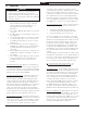
Notes:
1. If any of the original wire supplied with the appliance must
be replaced, it must be replaced with the same type shown or its equivalent.
Wire Type Legend
Low Voltage Factory Wiring size 18 AWG Type TEW/AWM stranded wire, 105°C
Line Voltage Factory Wiring size 14 AWG Type TW or TEW/AWM wire, 105°C
Line Voltage Field Wiring
Ignitor - NAT Gas: 16 AWG UL Style 3257, Honeywell 394803-2F, color RD (Red)
Low Voltage Factory Wiring size 18 AWG Type SF-2 stranded wire, 200°C
Low Voltage Field Wiring
Ignitor - LP Gas: 250°C (integral to pilot)
Ground Terminal
On Gas Valve
GND
L1
L2
Gas Valve
PV/MV
PV
MV
BL
RD
WH
WH
VI
VI
NO
C
Pressure
Switch
BL
VI
VI
2
1
Fan
WH
BK
BK
WH
WH
On/Off
Fan
P2
5
Fan
1 2
P2
3
P1
1
NOC
Pressure
Switch
P5
4
3
4
IDL 1200
LWCO
1
2
Auxiliary
Limit
Jumper
Jumper
LWCO
Sensing
Circuit
8.5
11.0
Burner
Demand
Contacts
Proof of
Pilot
Contacts
RD
RD
LWCO Connections
Lead
Blue
White
Red from Jumper Plug
Red to Flame Rollout Switch
PIN #
1
2
3
4
A
B
C
D
4
3
2
1
4
3
2
1
A
B
C
D
UNLESS OTHERWISE NOTED:
ALL DIMENSIONS IN INCHES.
TOLERANCES:
X.X ±.1 X.XXX ±.005
X.XX ±.03 ANGLE ±1°
THIS DOCUMENT CONTAINS CONFIDENTIAL INFORMATION
AND ITS CONTENTS ARE THE SOLE PROPERTY OF U.S. BOILER
COMPANY, INC. ANY REPRODUCTION IN PART OR AS A
WHOLE WITHOUT THE WRITTEN PERMISSION OF U.S. BOILER
COMPANY, INC. IS STRICTLY PROHIBITED.
THIRD ANGLE
PROJECTION
MATERIAL:
ITEM NUMBER:
FIRST USE:
TITLE:
DRAWING NUMBER:
DATE:
REVISION:
SIZE: C
SHEET: 1 OF 1
SCALE: 1:1
APVD: PS
CHK: JP
DES: JP
06/27/2019
X-PV, PVCG-C, BWF-B
109843-01
SEE NOTES
S9631A/IDL 1200 EQUIPPED
WIRING DIAGRAM SHEET
P1
109843-01
REVISIONS
REV.
EN DATE DESCRIPTION DWN CHK APVD
P1 104-35 - PRE-PRODUCTION - INITIAL RELEASE
JP JP
PS
Notes:
1. Material spec.: Plain white paper, size 8.5 x 11.0, printed double sided.
2. All borders, lettering, diagrams and logos to be black with white background.
Figure 9.4: Wiring Ladder Diagram
9 Wiring (continued)