
Install Instructions


34
109837-01 - 5/20
PVCG-C
Installation, Operating & Service Manual
CAUTION
Avoid operating this boiler in an environment
where saw dust, loose insulation fibers, dry wall
dust, etc. are present.
!
appliances on and off. The inlet pressure
at the boiler must be within the following limits
regardless of what combination of appliances is
firing:
Inlet Pressure
(in. w.c.) Natural Gas LP Gas
Minimum 4.5 11.0
Maximum 14.0 14.0
3. If the inlet pressure falls outside of these limits,
find and correct the cause of the problem
before proceeding further.
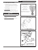
4. If boiler is installed with a Direct Vent
Conversion Kit, disconnect the regulator
tube from the hose barb on the gas valve
(Figure 10.4).
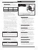
5. Connect a manometer to the manifold (outlet)
pressure tap on the gas valve (Figure 10.2).
6. Read the manifold pressure. It should be set at:
Natural Gas LP Gas
Manifold Press. (in. w.c.) 3.5 10.0
7. If a manifold pressure adjustment is needed,
make the adjustment by turning the regulator
screw (see Figure 10.2a) clockwise to raise the
pressure and counter-clockwise to reduce the
pressure. If a manifold pressure adjustment is
made, recheck the inlet pressure after making
the adjustment to be certain that it is still within
acceptable limits. Replace the cover screw on
the regulator.
8. If boiler is installed with a Direct Vent
Conversion Kit, reconnect the regulator tube to
the hose barb on the gas valve (Figure 10.4).
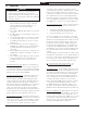
L. Check Main Burner Flame - See Figure 10.5.
Flame should have a clearly defined inner cone
with no yellow tipping. Orange-yellow streaks
caused by dust should not be confused with true
yellow tipping.
M. Check Pilot Burner Flame.
Natural Gas Only. Pilot produces single
flame. Flame should be steady medium hard
blue enveloping 3/8 to 1/2 inch of igniter/
sensor tip. See Figure 10.6.
LP Gas Only. The pilot burner produces three
(3) flames. The center flame should be steady,
medium hard blue enveloping 3/8 to 1/2 inch
of sensing probe. See Figure 10.7.
N. Gas valve safety shutdown test - With main
burners firing, disconnect ignition cable from
ignition module. Both pilot burner and main
burners should stop firing.
O. Check High Limit Control - Jumper thermostat
connections in boiler wiring harness. Allow
burners to operate until shutdown by limit (factory
setting is 180F). REMOVE JUMPER WHEN TEST
IS COMPLETE.
P. Check LWCO Operation – Push and hold the
LWCO TEST button while the boiler is firing
(Fig 10.1). The burners should shut down and
the yellow light illuminate on the LWCO. Upon
releasing the TEST button, the yellow light should
go off and the boiler fire.
Q. Check Thermostat Operation - Raise and lower
temperature setting to start and stop boiler
operation. Adjust thermostat to normal setting.
R. Check of External Safety Devices - Verify proper
operation of any field installed safety devices,
such as external limits.
S. Combustion Chamber Burn-off
1. The mineral wool combustion chamber panels
may contain a cornstarch based binder that
must be burned out at installation to prevent
odors during subsequent boiler operation.
WARNING
Failure to connect the regulator tube to the air
box or replace the regulator screw cover after
making a manifold pressure adjustment, could
cause elevated CO levels on direct vent boilers
resulting in personal injury or loss of life.
!
Figure 10.4: Regulator Tube Location On Gas Valve
(Direct Vent Boilers Only)
10 Start-up and Checkout (continued)