
Install Instructions


42
109837-01 - 5/20
PVCG-C
Installation, Operating & Service Manual
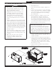
D. Sequence Of Operation
(Refer to Figures 9.3 or 9.4 for Connection and
Ladder diagrams)
1. A call for heat from the thermostat energizes
the Heating Circulator (connected to red and
white leads in j-box).
2. Depending on the boiler water temperature at
the time of the call for heat, the control will do
one of two things:
• If the water temperature is below the ther-
mal purge start temperature (St), the con-
trol will continue the ignition sequence.
• If the boiler water temperature is above
the thermal purge start temperature, the
boiler will wait until either of the following
conditions are met before continuing the
ignition sequence:
a. The boiler water temperature falls be-
low the thermal purge start tempera-
ture (St) Factory default is 140F.
b. The thermal purge time elapses (PP).
Factory default is 2 minutes.
3. If the flame roll-out switch, and LWCO con-
tacts are made, the control will verify that the
air pressure switch (APS) is open before start-
ing the fan.
4. The control energizes the fan and waits for the
air pressure switch to close.
5. Once the air pressure switch closes, the con-
trol waits for a 30s “prepurge period” to pass
before attempting to light the pilot.
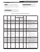
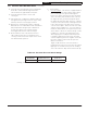
Table 11.8: Summary of Circulator Behavior
Thermostat Inputs
Use of
“DHW”
Zone
Parameters Circulator Outputs
T- T “DHW”
2nd
Zone
(dh)
DHW
Priority
(Pt)
Heating
(Yellow Circ. Lead)
“DHW”
(Red Circ. Lead)
ON OFF DHW
dh=dh ON
ON OFF
OFF ON DHW
dh=dh ON
OFF ON
ON ON DHW
dh=dh ON
OFF ON
ON ON DHW
dh=dh OFF
ON ON
ON OFF DHW
dh=dh OFF
ON OFF
OFF ON DHW
dh=dh OFF
OFF ON
ON OFF Heat
dh=tt2 ON or OFF
ON OFF
OFF ON Heat
dh=tt2 ON or OFF
OFF ON
ON ON Heat
dh=tt2 ON or OFF
ON ON
6. The control starts an ignition spark at the pilot
and applies 24 volts across the pilot valve
(terminals PV and MV/PV on the gas valve).
7. Once the pilot is established, the pilot flame
will act as a diode, converting the AC current
at the electrode to a half wave DC current at
the pilot’s ground strap. This DC current flows
through the boiler to the ground connection
on the S9361A. For the ignition module to
recognize that a pilot flame is present, the DC
current flowing into this terminal must be in
excess of approximately 1.0 uA.
8. If the pilot is not proven within 60 seconds of
the beginning of the trial for ignition, the pilot
valve will close and wait 5 minutes before the
ignition sequence is retried.
9. Once the ignition module detects the pres-
ence of a pilot flame, voltage is applied
across the main valve (terminals MV and MV/
PV on the valve), opening the valve and es-
tablishing main flame.
10. If the water temperature climbs above the
high limit setting during the call for heat, the
burner and blower will shut down while the
Heating Circulator continues to operate. The
ignition sequence will restart (from Step 3)
when the water temperature falls to the high
limit setting (HL) minus the high limit differen-
tial (HdF).
11. A call for DHW results in a sequence of opera-
tion that is identical to that described above
except for omission of the thermal purge func-
tion described in (2).
11 Operation (continued)