
Install Instructions


46
109837-01 - 5/20
PVCG-C
Installation, Operating & Service Manual
7. Inspect the ignition cable insulation for cracks
or other deterioration. If deterioration is found,
replace cable.
8. Reinstall burners, being careful to put the pilot
main burner in its original location.
9. Inspect all boiler wiring for loose connections or
deterioration.
10. Inspect the vent system:
• Make sure that the vent system,
and condensate disposal system, is free of
obstructions. Clean as necessary.
• Make sure that all vent system supports are
intact.
• Inspect joints for signs of condensate or flue
gas leakage.
• Inspect venting components for corrosion
or other deterioration. Replace any defective
vent components.
11. Inspect the boiler and hydronic system for leaks.
12. If the boiler is equipped with a Direct Vent
Conversion Kit:
• Check the air intake system, including the
air inlet terminal and air distribution screen
(Fig 12.1), for blockages, corrosion, or other
deterioration.
• Verify that the regulator reference hose is
clear and has not deteriorated.
13. Place the boiler back in operation using the
procedure outlined in “Start-up”. Check the pilot
line and any other gas piping disturbed during
the inspection process for leaks.
B. Heat Exchanger Cleaning Procedure
1. Turn off electrical power and gas supply to the
boiler.
2. Remove the burner door, pilot, and all burners.
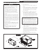
3. Disconnect the vent system by removing the
screws shown in Figure 6.10 and sliding the vent
adaptor off of the fan.
4. Remove the top jacket panel. If possible,
remove the rear and left side jacket panels.
5. Unplug the fan.
6. Disconnect the pressure switch hoses from
the pressure switch being careful to note their
orientation.
7. Remove the four #10 sheet metal screws holding
the canopy onto the block. Also remove the four
sheet metal screws securing the canopy to the
side jacket panels.
8. Remove the canopy/fan from the heat
exchanger.
9. Carefully remove the canopy gasket strips and
set them aside.
10. Remove the stainless steel flue baffles from the
flue passages. Clean them of any deposits and
set them aside.
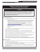
WARNING
Soot deposits in the flue passages are a sign that the boiler may be operating at high carbon monoxide (CO)
levels. After cleaning the boiler of soot deposits, check the CO level in the flue gas to insure that the boiler is
operating properly.
If it is necessary to check CO, use a combustion analyzer, or other instrument which is designed to measure
CO in flue gas. A CO “sniffer” designed for testing CO levels in ambient air cannot be used to check boiler
combustion. Take a flue gas sample by inserting a sample probe through the vent terminal. Do not take a
sample until the boiler has been firing for at least five minutes. A normal CO reading for this series boiler is less
than 50ppm (0.005%). A reading of more than 100ppm (0.01%) is indicative of a combustion problem.
Some causes of excessive CO include:
• Incorrectly sized or drilled burner orifice
• Partially plugged flue passages
• Improper manifold pressure
• Partial blockage of vent or intake system
• Foreign material in burner venturis or burner ports
• Damaged fan impeller or housing
• Damaged or missing fan gasket
• Leak in seal between canopy and heat exchanger
• Distorted or missing combustion chamber floor or baffles
• Damaged base
!
12 Service and Maintenance (continued)