
Install Instructions


53
109837-01 - 5/20
PVCG-C
Installation, Operating & Service Manual
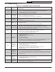
Key
No.
Description
Part Number [Quantity]
3 Section 4 Section 5 Section 6 Section 7 Section 8 Section
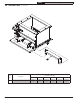
2A Base Wrapper
110401-03
[1]
110401-04
[1]
110401-05
[1]
110401-06
[1]
110401-07
[1]
110401-08
[1]
2B Base Tray
2C Burner Tray Assembly
2D Base Side Insulation
2E Base Rear Insulation
2F Base Front Insulation
2G Drip Shields
2H Base Front Panel
2I Base Leg Assembly
2J Base Gasket Kit
2K Manifold Support Bracket
2L Burner Access Panel
2M Flame Rollout Switch
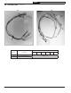
3D
Main Burner with Pilot
Bracket
3F
Main Burners less Pilot
Bracket
2J Base Gasket Kit 6206002 [1]
2L Burner Access Panel
110403-03
[1]
110403-04
[1]
110403-05
[1]
110403-06
[1]
110403-07
[1]
110403-08
[1]
2M
Flame Rollout Switch
G4AM0600240C
109616-01 [1]
14 Service Parts (continued)
WARNING
If base must be replaced,
there is a good chance pilot
assembly and pilot tubing
will need to be replaced
as well. Replacement pilot
assemblies are shown
on page 54. Also check
condition of manifold and
gas valve and replace if
they show any signs of heat,
corrosion, or water damage.
!