
Install Instructions


61
109837-01 - 5/20
PVCG-C
Installation, Operating & Service Manual
Appendix A: Direct Vent Installations
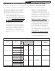
Table A.2 Summarizes all direct vent options. One of
the columns in Table A.2 must describe the planned
direct vent system exactly. In addition, observe the
following guidelines:
A. Direct Vent Conversion Kit Installation on the
Boiler - Follow the instructions provided with the
kit to install the Direct Vent Conversion Kit on the
boiler.
B. Vent System Design and Assembly –
Vent system is assembled using installer
supplied AL29-4C stainless steel vent
components. See Section 6 for detailed
instructions on vent system design and
assembly. Exception: In some cases,
clearances from vent terminals are different
when the boiler is direct vented. See
“Horizontal Terminal Location” in this section.
C. Intake System Design -
1. Intake Piping Materials – Any of the following
materials may be used between the intake
collar on the boiler and the intake terminal:
• 26 gauge galvanized vent pipe.
• Schedule 20 or 40 PVC
2. Intake Piping Sizes and Maximum Lengths –
Maximum intake lengths and intake pipe
nominal diameters are shown in Table A.2.
For each elbow used on the intake system,
reduce the maximum allowable length by
the amount shown in Table A.8. Note that no
reduction is made for the intake terminal.
Example
A 3” air intake system is planned for a
horizontal direct vented 105000 BTU/hr
boiler which has the following galvanized
components:
2 ft vertical pipe
1 90 elbow
5 ft horizontal pipe
1 90 elbow
3 ft horizontal pipe
1 termination fitting
The Vent Option #5 column in Table A.2
describes a horizontal direct vent system
using 3” intake pipe. From this column, we
see that this boiler may have an intake
piping system of up to 60ft. From Table
A.8 the equivalent length of the 3” 90 degree
galvanized elbow is 5.5ft. The maximum
allowable run of straight pipe on this system is
therefore:
60ft – 5.5ft – 5.5ft = 49ft
Since the planned installation has only
10ft of straight pipe, the planned intake length
is acceptable.
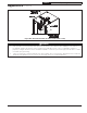
WARNING
Failure to install the intake box and other
components on the boiler as described in the
Direct Vent Conversion Kit instructions could
cause the boiler to operate at elevated Carbon
monoxide (CO) levels resulting in personal
injury or loss of life.
!
This Appendix describes how to bring
combustion air directly from outside to the boiler
(direct venting) using the Direct Vent Conversion
Kits shown in Table 2.2. These kits includes an air
box and other components needed to route air
directly to the combustion chamber, as well as an
air intake terminal for horizontal installations. By
using these kits to route combustion air directly
to the boiler, the need to obtain such air from
within the structure is eliminated. This is often
advantageous in tightly constructed buildings.
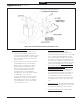
Figure A.1 shows the boiler with the Direct Vent
Conversion Kit installed and the location of the air
inlet connection.
Figure A.1: Boiler With Direct Vent Conversion Kit
Installed (Front Door Omitted for Clarity)