
Install Instructions


63
109837-01 - 5/20
PVCG-C
Installation, Operating & Service Manual
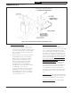
4. Horizontal terminal location – Install the
intake terminal to either side of the
exhaust terminal as shown in Figure A.4.
The intake terminal must be on the same wall
as the exhaust terminal. Maintain at least
12” from the intake terminal to the exhaust
terminal as shown. Also note that when this
kit is used, the exhaust terminal must be at
least 1 foot from any door, window, or gravity
inlet into the building. This is less than the
4ft clearance shown in Section 6 for boilers
using indoor combustion air.
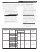
5. Vertical terminal location - Install the intake
terminal as shown in Figure A.6 or A.7.
The vertical distance between vent and air
inlet terminal openings must be at least
12”. The bottom of the air inlet terminal
must be at least 12” above the normal snow
accumulation that can be expected on the
roof.
6. Terminal Offsets – When horizontal terminals
are offset as shown in Figure A.5, both must
be offset vertically by the same distance.
7. Support of Intake Piping – Support intake
piping every 5 feet.
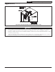
3. Permitted Intake Terminals –
a. Horizontal venting applications use the
terminal provided with the Direct Vent
Conversion Kit. Install this terminal so that
it is flush with the wall as shown in Figure
A.3. Seal the terminal to the wall using
silicone caulk.
b. Vertical systems use either the terminal
provided with this kit or a 180 degree
elbow (either a single fitting or two 90
degree elbows) as shown in Figure
A.6 or A.7. Note that the 180 elbow
is preferred if the intake terminal is
frequently exposed to wind-driven
rain. Except in very cold climates where
ice build-up is a concern, it is
recommended that a rodent screen be
installed in the end of the 180 degree
elbow. When this is done, use stainless
steel, galvanized steel, or non-metallic
screen having ½” mesh.
Figure A.4: Horizontal Direct Venting (Vent Options 5-7)
Appendix A (continued)